Welcome to the World of Sensors and Modules with Arduino!
In this guide I will be exploring RFID modules, in particular, the RC522 module found in Elegoo’s Most Complete Starter Kit. This module allows you to read data from RFID cards and tags. Whether you’re a beginner looking to get started or someone with a bit of experience, seeking to expand your knowledge, this guide will cover the essentials of RFID technology. First, you’ll learn how RFID technology works. Next, you’ll explore RFID module functionality, their components, and practical ways to use them in your projects. By the end, you’ll be ready to unlock the potential of RFID for various applications.
If you’re new to Arduino, why not take a look at our Getting Started with Arduino guides. These guides are designed for beginners to learn the fundamental basics of Arduino programming.
What is RFID?
RFID stands for Radio Frequency Identification.
It’s a technology that uses electromagnetic fields to automatically identify and track objects, animals, or people. This is typically done using an RFID tag (or card) and an RFID reader.
Here’s how it works:
- RFID Tag: Contains a small microchip and antenna. The chip stores data, such as the UID.
- RFID Reader: Emits radio waves to power the tag (in passive systems) and reads the data transmitted back from the tag.
RFID is widely used in applications like access control, inventory tracking, toll collection, and contactless payments.
What is UID?
RFID cards and key fobs generally come preloaded with unique UIDs (Unique Identifiers). Here’s some more detail:
UID Basics
- The UID is a unique serial number assigned to each RFID card by the manufacturer.
- It is burned into the card during manufacturing and cannot be changed.
- The UID is used to identify the card and is read-only.
Variations in UID Length
- 4-byte UID: Common in standard MIFARE cards.
- 7-byte UID: Used in some advanced or high-security cards.
- 10-byte UID: Less common but can be found in some specialized RFID systems.
The length depends on the card type and the standards it adheres to (e.g., ISO/IEC 14443).
Are UIDs Unique?
- Manufacturers ensure that UIDs are unique across their production batches, meaning no two cards from the same batch will have the same UID.
- However, in rare cases, across different manufacturers or counterfeit cards, duplicate UIDs can exist.
Applications of UIDs
- UIDs are often used for access control, inventory tracking, or identification in systems that require a simple unique identifier.
- Since UIDs cannot be changed, they are ideal for basic card identification but not for dynamic data storage or encryption.
What If You Need Changeable Identifiers?
If you need cards with identifiers that you can program, you can use the writable data blocks on the card. These blocks allow you to store and update custom information, but the UID will remain constant.
How to use the RC522 Module with Arduino
In this section, we’ll guide you step-by-step through the process of working with the RC522 module. Each step will cover a critical aspect of the setup, ensuring you have all the information needed to successfully complete your project.
Necessary Equipment: A list of tools and components required.
Pin Configuration: Details on connecting the RFID module to your microcontroller.
Necessary Libraries: Software dependencies to get the module running.
Test Code: A simple example to verify everything is working as expected.
By following along, you’ll gain the confidence to build and troubleshoot your own RFID-based systems. Let’s get started!
Necessary Equipment
Ensure you have all the necessary equipment before starting:
- Arduino (e.g., Arduino Uno, Nano etc…)
- RC522 Module
- RFID Card
- RFID Key Fob
- Jumper wires
- Breadboard (optional)
The RC522 module uses RFID technology to identify and communicate with tags, fobs or cards.
Features and Specifications:
- Frequency: 13.56 MHz
- Dimensions: 39.5mm (width) x 60mm (length) x 1.5mm (thickness)
- Protocols Supported: ISO 14443A
- Communication Interface: SPI (Serial Peripheral Interface)
- Voltage: 3.3V
- Range: Up to 5 cm, depending on the tag and environmental conditions
- Low power consumption
Pin Configuration
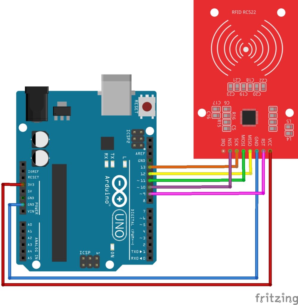
Connect the RC522 Module to your Arduino Uno board as follows:
- VCC on the RFID Module to 3.3V on the Arduino.
- GND on the RFID Module to GND on the Arduino.
- SDA (Chip Select) on the RFID Module to Digital Pin 10 on the Arduino.
- SCK (Serial Clock) on the RFID Module to Digital Pin 13 on the Arduino.
- MOSI (Master Out Slave In) on the RFID Module to Digital Pin 11 on the Arduino.
- MISO (Master In Slave Out) on the RFID Module to Digital Pin 12 on the Arduino.
- RST (Reset) on the RFID Module to Digital Pin 9 on the Arduino.

Necessary Libraries
To use the RC522 Module, we need to install a specific library. You can install this library within the Arduino IDE by following these steps:
- Open the Arduino IDE.
- Go to Tools > Manage Libraries.
- Search for MFRC522 and install it.
Test Code:
With the library installed to the IDE, we can test out setup with an example sketch found in the MFRC522 library. In the Arduino IDE, navigate to:
File > Examples > MFRC522 > DumpInfo.
The DumpInfo.ino sketch reads data from the RFID card and displays the data collected to the serial monitor. It also allows us to check if everything is setup correctly. Continue with the next steps to complete testing:
- Upload the DumpInfo sketch to your Arduino.
- Open the Serial Monitor.
- Bring an RFID card or tag close to the module. You should see information about the card, such as its UID and memory contents.
- Make a note of the UID for each card or tag you will be using.
RC522 Module Code Examples
Now we are all set up, and everything is working, we can start creating projects using the RFID Module.
Here are two examples of RFID access systems:
Basic RFID Access System with the RC522 Module
Here’s a simple project using the RFID module and the key card. When you scan the key card, the system checks the UID of the card and allows or denies access based on whether the UID matches a predefined value.
Take a look at the code below:
#include <SPI.h>
#include <MFRC522.h>

#define RST_PIN 9  // Reset pin
#define SS_PIN 10  // SDA pin

MFRC522 mfrc522(SS_PIN, RST_PIN);  // Create MFRC522 instance

// Replace with your RFID key card UID
byte allowedUID[] = {0xDE, 0xAD, 0xBE, 0xEF};  // Example UID, replace with your card's UID

void setup() {
  Serial.begin(9600);  // Initialize serial communication
  SPI.begin();         // Initialize SPI bus
  mfrc522.PCD_Init();  // Initialize MFRC522
  Serial.println("Scan your RFID key card to access.");
}

void loop() {
  // Check if a card is detected
  if (!mfrc522.PICC_IsNewCardPresent() || !mfrc522.PICC_ReadCardSerial()) {
    return;
  }

  Serial.print("Card UID: ");
  for (byte i = 0; i < mfrc522.uid.size; i++) {
    Serial.print(mfrc522.uid.uidByte[i], HEX);
    Serial.print(" ");
  }
  Serial.println();

  // Check if the scanned UID matches the allowed UID
  if (isUIDAllowed(mfrc522.uid.uidByte, mfrc522.uid.size)) {
    Serial.println("Access Granted!");
    // Add code here for actions (e.g., unlock a door, turn on an LED)
  } else {
    Serial.println("Access Denied!");
    // Add code here for denied actions (e.g., sound a buzzer)
  }

  // Halt communication with the card
  mfrc522.PICC_HaltA();
}

// Function to compare UIDs
bool isUIDAllowed(byte *uid, byte uidSize) {
  if (uidSize != sizeof(allowedUID)) {
    return false;
  }
  for (byte i = 0; i < uidSize; i++) {
    if (uid[i] != allowedUID[i]) {
      return false;
    }
  }
  return true;
}
Breaking Down the Code
Here’s a complete breakdown of the RFID card access system code:
Library Inclusions
We start by including two libraries:
SPI.hallows communication between the Arduino and the RFID module using the SPI protocol.MFRC522.hprovides functions for working with the RC522 RFID module.
Pin Definitions and RFID Instance
The RST_PIN and SS_PIN are defined to indicate which Arduino pins are connected to the RFID module’s reset and SDA pins. An MFRC522 object is created to control the RFID module.
Allowed RFID UID
The allowedUID array stores the UID (Unique Identifier) of the allowed card. You should replace the placeholder values with the UID of your own RFID card.
The Setup Function
- Serial communication is initialized using
Serial.begin(9600), so you can monitor the outputs in the Serial Monitor. SPI.begin()initializes the SPI bus for communication.mfrc522.PCD_Init()sets up the RFID module.- A welcome message is printed to the Serial Monitor.
The Main Loop
The loop first checks if a card is near the module using PICC_IsNewCardPresent(). If no card is detected, the loop returns early and waits for a card.
Display UID
If a card is detected, the UID is read and displayed on the Serial Monitor. Each byte of the UID is printed in hexadecimal format.
Check UID
The isUIDAllowed function is called to compare the detected card’s UID with the predefined allowed UID. If the UIDs match, the Serial Monitor prints “Access Granted!” Otherwise, it prints “Access Denied!”
Halt Communication
After checking the card, mfrc522.PICC_HaltA() halts communication with the current card, preparing the module for the next scan.
Compare UID Function
The isUIDAllowed function compares the detected UID with the allowed UID. It first checks if the lengths of the two UIDs match. If they don’t, it returns false. Then, it compares each byte of the two UIDs. If all bytes match, it returns true, granting access.
How to Use the RC522 Module
- First, you need to edit the
allowedUID[]within the Basic RFID Access System sketch to match the UID of a RFID card you noted down earlier:DE AD BE EFwould be written like0xDE 0xAD 0xBE 0xEFjust like in the byte array
- Next, upload this sketch to your Arduino.
- Open the Serial Monitor (set to 9600 baud).
- Finally, scan your RFID key card.
If done correctly you should see an “Access Granted” message display to the serial monitor. Now scan the fob instead, you should see an “Access Denied” message display to the serial monitor. This is because the UID of the fob was not entered into the sketch.
That’s it, that’s the Basic RFID Access System. Now let’s expand on this project by adding a little more functionality.
Using LED’s and Servo with the RC522 Module
In this next project we will be adding a Green LED and Red LED for a visual representation of access be granted or denied, and we will be adding a servo to simulate the door opening when access is granted. If you have one, you could use a solenoid lock instead of the servo. You will need to make adjustments to your circuit to make sure the solenoid lock has an appropriate power supply. To keep things simple for this guide, I will be using a servo motor instead.
Pin Configuration
Keep the RC522 Module connected to the Arduino the same as before, but now we include the connections for a servo and LED’s. The connections are as follows:
- RED LED:
- Connect the Cathode(-) (short leg) of the LED to GND on the Arduino.
- Connect the Anode(+) (long leg) of the LED to Digital pin 7 on the Arduino. (Make sure you use a current limiting resistor in between the LED and pin 7, to protect the LED).
- GREEN LED:
- Connect the Cathode(-) (short leg) of the LED to GND on the Arduino.
- Connect the Anode(+) (long leg) of the LED to Digital pin 6 on the Arduino. (Make sure you use a current limiting resistor in between the LED and pin 6, to protect the LED).
- Servo:
- VCC of the Servo to 3.3v on the Arduino.
- GND of the servo to GND on the Arduino.
- PWM/Signal of the servo to Digital pin 3 on the Arduino.

Arduino Code Example
Here is a working code example that simulates a working access control system. Firstly, don’t forget to edit the authorizedUID[] code number to match your own RFID card or key fob. Finally, when you’re ready, upload this code to your Arduino.
#include <SPI.h>
#include <MFRC522.h>
#include <Servo.h>

#define RST_PIN 9
#define SS_PIN 10
#define GREEN_LED 6
#define RED_LED 7

Servo myServo;
MFRC522 mfrc522(SS_PIN, RST_PIN);

// Define authorized UID
byte authorizedUID[] = {0xE5, 0x09, 0xCE, 0x23};

void setup() {
  Serial.begin(9600);
  SPI.begin();
  mfrc522.PCD_Init();

  pinMode(GREEN_LED, OUTPUT);
  pinMode(RED_LED, OUTPUT);

  myServo.attach(3); // Servo connected to pin 3
  myServo.write(0);  // Set servo to initial (closed) position

  Serial.println("Scan an RFID card...");
}

void loop() {
  // Look for a new RFID card
  if (!mfrc522.PICC_IsNewCardPresent() || !mfrc522.PICC_ReadCardSerial()) {
    return;
  }

  if (isAuthorized(mfrc522.uid.uidByte, mfrc522.uid.size)) {
    grantAccess();
  } else {
    denyAccess();
  }

  mfrc522.PICC_HaltA();
}

bool isAuthorized(byte *scannedUID, byte uidSize) {
  for (byte i = 0; i < uidSize; i++) {
    if (scannedUID[i] != authorizedUID[i]) {
      return false;
    }
  }
  return true;
}

void grantAccess() {
  Serial.println("Access Granted");
  digitalWrite(GREEN_LED, HIGH);
  digitalWrite(RED_LED, LOW);

  myServo.write(90); // Simulate opening door
  delay(3000);       // Keep door open for 3 seconds
  myServo.write(0);  // Close door

  digitalWrite(GREEN_LED, LOW);
}

void denyAccess() {
  Serial.println("Access Denied");
  digitalWrite(GREEN_LED, LOW);
  digitalWrite(RED_LED, HIGH);
  delay(2000); // Keep red LED on for 2 seconds
  digitalWrite(RED_LED, LOW);
}
Breaking Down the Code
I’m not going to give a complete breakdown here as much of the code is the same as the basic access control code we covered before. Instead, I’ll just give a breakdown of the newly added functions which control the Servo and LEDS.
Grant Access Function (grantAccess)
- Purpose: Executes when an authorized card is detected.
- What It Does:
- Lights up the green LED to indicate access is granted.
- Moves the servo motor to simulate a door opening:
- The servo turns to 90 degrees to “open the door.”
- After a delay (3 seconds), it returns to 0 degrees to “close the door.”
- Turns off the green LED after the sequence.
digitalWrite(GREEN_LED, HIGH); // Green LED ON
myServo.write(90); // Open door
delay(3000); // Wait for 3 seconds
myServo.write(0); // Close door
digitalWrite(GREEN_LED, LOW); // Green LED OFF
Deny Access Function (denyAccess)
- Purpose: Executes when an unauthorized card is detected.
- What It Does:
- Lights up the red LED to indicate access is denied.
- Keeps the red LED on for 2 seconds, then turns it off.
digitalWrite(RED_LED, HIGH); // Red LED ON
delay(2000); // Wait for 2 seconds
digitalWrite(RED_LED, LOW); // Red LED OFF
Servo Initialization in setup
- Purpose: Prepares the servo motor for operation.
- What It Does:
- Attaches the servo to pin 3.
- Sets the servo to its initial position (0 degrees, door closed).
myServo.attach(3); // Connect servo to pin 3
myServo.write(0); // Set servo to initial position (closed)
LED Pin Definitions
- Two new pins are defined for the LEDs:
#define GREEN_LED 6 // Green LED for access granted
#define RED_LED 7 // Red LED for access denied
These variables ensure clarity and make it easy to modify pin assignments if needed.
This breakdown covers the logic for the added components, highlighting how they enhance the functionality of the original RFID system.
Once your sketch is uploaded to the Arduino, you can go ahead and scan your RFID card or key fob. If all was done correctly the Green LED will illuminate and the servo will move to simulate the door lock opening.
Applications and Usage Scenarios
Here are a few more ideas for other projects you can create using the RC522 module:
Attendance System:
Log attendance by scanning RFID tags for individuals.
Cashless Payment:
Simulate a payment system where each RFID tag has a “balance.”
Inventory Management:
Track tagged items in a warehouse.
Conclusion
Congratulations! By following this guide, you’ve built a functional RFID-based system that includes LED indicators and a servo-controlled door mechanism. This project demonstrates the versatility and practicality of RFID technology in real-world applications. With the skills and understanding you’ve gained, you can further customize this project by adding features like multiple authorized users, a display screen, or even Wi-Fi connectivity for remote access control.
The possibilities with RFID technology are vast, and this is just the beginning. We hope this guide has inspired you to explore more advanced projects and make RFID a key part of your innovative creations. Happy building!
Discover the endless possibilities for Arduino projects with more of our Sensors and Modules guides.


Your article truly stood out to me for its clear, insightful analysis of current trends. I found it incredibly helpful and refreshing—a standout piece in a sea of ordinary posts. Thank you for sharing such a resourceful perspective.