


Welcome to the World of Sensors and Modules with Arduino!
The Reed Switch Sensor Module is a fascinating component that leverages magnetic fields for simple yet versatile applications in electronics. In this sensors and modules guide, we’ll explore its working principle, key features, applications, and how it can enhance your Arduino projects.
If you’re new to Arduino, why not take a look at our Getting Started with Arduino guides. These guides are designed for beginners to learn the fundamental basics of Arduino programming.
How the Reed Switch Sensor Module Works
Reed Switch Sensors consist of two ferromagnetic reeds housed within a sealed enclosure, commonly made of glass or plastic. These reeds, when in their natural state, remain separated due to their springiness, creating an air gap between them. This separation keeps the circuit open, and no current flows through the switch.
When a magnet is brought close to the reed switch, it generates a magnetic field around the switch. The magnetic field influences the reeds, causing them to attract each other and connect (close) momentarily, overcoming their spring tension. This closure completes the circuit, allowing current to flow through the switch.
Once the magnetic field is removed or moved away, the reeds lose the magnetic influence, returning to their natural state. The reeds spring back to their separated position (open), breaking the circuit, and no current flows through the switch. In summary, Reed switches act as simple on/off switches, responding to the presence or absence of a magnetic field.
Features and Specifications:
- Operating Voltage: 5V
- Magnetic Sensing: Detects the presence or absence of a magnetic field.
- Output: Offers both analog and digital output signals to indicate the distance to detected obstacles.
- Sensitivity: Adjustable by Trimmer Potentiometer
- Size: 42.5mm x 15mm
- Compatibility: This sensor is also compatible with other devices like the Raspberry Pi, ESP32, and ESP8266 etc…
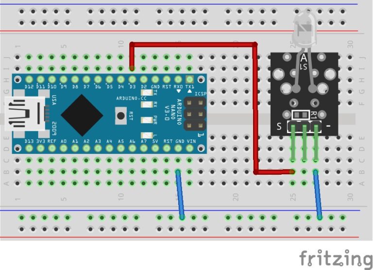
Necessary Equipment:
- Arduino board (e.g., Arduino Uno)
- Reed Switch Sensor Module
- Jumper wires
- Breadboard (optional)
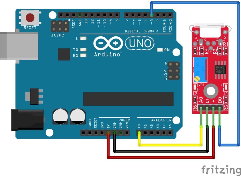
Pin Configuration
Connecting the Reed Switch Sensor Module to an Arduino is fairly simple. The connections are as follows:
- A0 on the Reed Switch Sensor Module to A0 on the Arduino (or any analog pin).
- G on the Reed Switch Sensor Module to GND on the Arduino.
- + on the Reed Switch Sensor Module to 5V on the Arduino.
- D0 on the Reed Switch Sensor Module to Digital pin 3 on the Arduino (or any digital pin).
Pin labels may vary.
KY-025 Reed Switch Module Fritzing Part is created by arduinomodules.info and published under Creative Commons Attribution-ShareAlike 4.0 International license
Why Take Analog and Digital Readings?
Reed switch modules often provide both digital and analog outputs, offering different types of information about the detected magnetic field. Here’s why you might want to read both digital and analog values:
Digital Reading:
- Magnetic Field Presence: The digital output provides a straightforward indication of whether a magnetic field is detected or not. It’s a binary signal, typically HIGH or LOW, indicating the presence or absence of a magnetic field respectively.
- Simple On/Off State: Useful for basic proximity sensing or triggering actions when a magnet is near the reed switch. For example, activating an alarm when a door is opened.
Analog Reading:
- Quantitative Measurement: The analog output provides a range of values based on the strength or proximity of the magnetic field. This analog signal varies within a range (0 to 1023 on Arduino) and offers more nuanced information about the field’s intensity.
By reading both digital and analog values from the reed switch module, you can gather different types of information about the detected magnetic field. The digital output gives a simple presence or absence signal, while the analog output provides more detailed information about the field’s strength or proximity, allowing for more nuanced and precise sensing capabilities in your projects.
Arduino Code Example
const int digitalPin = 3; // Reed switch digital interface
const int analogPin = A0; // Reed switch analog interface

void setup() {
  pinMode(digitalPin, INPUT); // Reed switch digital pin as input
  pinMode(analogPin, INPUT); // Reed switch analog pin as input
  Serial.begin(9600); // Start serial communication
}

void loop() {
  int digitalVal = digitalRead(digitalPin); // Read digital value
  int analogVal = analogRead(analogPin); // Read analog value

  Serial.print("Digital Value: "); // Print digital value to Serial Monitor
  Serial.println(digitalVal);

  Serial.print("Analog Value: "); // Print analog value to Serial Monitor
  Serial.println(analogVal);

  delay(100); // Delay for readability in Serial Monitor
}
Breaking Down the Code
Pin Declaration
const int digitalPin = 3;andconst int analogPin = A0;Defines the digital and analog pins connected to the reed switch module.
Setup Function
void setup() { ... }: The setup function runs once when the Arduino starts.pinMode(digitalPin, INPUT);andpinMode(analogPin, INPUT);: Configures the specified pins as inputs to read digital and analog values.Serial.begin(9600);: Starts serial communication at a baud rate of 9600.
Loop Function
void loop() { ... }: The loop function runs continuously after the setup.int digitalVal = digitalRead(digitalPin);: Reads the digital value from the reed switch module.int analogVal = analogRead(analogPin);: Reads the analog value from the reed switch module.int mappedVal = map(analogVal, 1023, 0, 0, 100);: Maps the analog values from their original range (0-1023) to a new range (0-100).Serial.print("Digital Value: ");andSerial.print("Analog Value: ");: Prints text labels to the Serial Monitor.Serial.println(digitalVal);andSerial.println(mappedVal);: Prints the digital and mapped analog values to the Serial Monitor.delay(100);: Introduces a delay of 100 milliseconds for readability in the Serial Monitor.
This code continuously reads and displays the digital and mapped analog values from the reed switch module to help monitor the behavior of the sensor in response to magnetic fields. Adjustments to the mapping range can be made to suit specific application requirements.
Applications and Usage Scenarios
Security Systems
Reed switches are integral components in magnetic door and window sensors, alerting when doors or windows are opened or closed.
Automotive Industry
Used in car alarm systems, trunk and hood detection, and gear shift position sensing.
Industrial Machinery
Employed in machinery for position detection, limit switches, and conveyor belt alignment.
Home Automation
Integrated into smart home devices for controlling lights, detecting door states, or activating appliances.
Appliance Control
Used in washing machines or dishwasher doors to detect closure for safe operation.
Magnetic Latches
Applied in cabinets, gates, or access control systems.
Mobile Devices
Utilized in smartphones and tablets to activate sleep mode when the cover is closed.
Magnetic Switches in Cases
Embedded in tablet or laptop cases to trigger sleep mode when closed.
Sump Pumps
Reed switches monitor water levels in sump pumps to prevent flooding.
Fluid-Level Sensing
Used in coffee machines or vending machines for monitoring liquid levels.
Automated Gardening Systems
Employed in soil moisture sensors or rain detectors for irrigation control.
Pet Feeders
Integrated into automated pet feeders to detect food levels.
Conclusion
In this sensors and modules guide, we explained the functionality of the Reed Switch Sensor Module, exploring its working principles, and demonstrating how to interface it with an Arduino for practical applications. Reed Switch Sensor Modules find extensive applications due to their simplicity, reliability, and versatility in detecting magnetic fields and position changes. Their use spans across diverse industries, from security and automotive to consumer electronics and IoT projects. Understanding their operation and effective integration paves the way for innovative solutions in electronics and automation.
Discover the endless possibilities for Arduino projects with more of our Sensors and Modules guides.