
What is an RGB?
An RGB LED is a type of light-emitting diode (LED) that can produce multiple colors by mixing different intensities of red (R), green (G), and blue (B) light. It combines three individual LEDs, one for each color component, into a single package. By controlling the brightness of each of these three colors, you can create a wide range of colors (16 million+). This guide will walk you through programming RGB LEDs with Arduino.
Components:
To use an RGB LED with an Arduino, you’ll need the following components:
An RGB LED: This is the actual LED that emits red, green, and blue light. It has four leads: one for each color (R, G, B) and one for the common cathode (ground).
An Arduino board: Any Arduino board will work. In this example, we’ll assume you’re using an Arduino Uno.
Three current-limiting resistors: You’ll need one resistor for each color (R, G, B). The value of these resistors depends on the forward voltage and forward current of your RGB LED. You can find this information in the LED’s datasheet or by experimenting. Typically, values between 220-470 ohms are a good starting point.
Jumper wires: To connect the components together.
Let’s Build!
Here’s a step-by-step guide to connect and control an RGB LED with an Arduino:
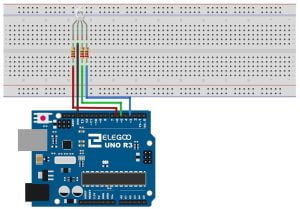
Step 1: Wiring
Connect the components as follows:
- Connect the common cathode of the RGB LED (the longer lead) to the GND (ground) pin on the Arduino.
- Connect the red (R) lead of the RGB LED to a digital pin on the Arduino (e.g., pin 6).
- Connect the green (G) lead of the RGB LED to another digital pin (e.g., pin 5).
- Connect the blue (B) lead of the RGB LED to a third digital pin (e.g., pin 3).
- Connect a current-limiting resistor to each of the three RGB LED leads (R, G, B). Connect the other end of each resistor to the respective Arduino pins.
Step 2: Arduino Code
Here’s a simple Arduino sketch to control the RGB LED:
const int redPin = 6;
const int greenPin = 5;
const int bluePin = 3;

void setup() {
  pinMode(redPin, OUTPUT);
  pinMode(greenPin, OUTPUT);
  pinMode(bluePin, OUTPUT);
}

void loop() {
  // Set the colors by varying the brightness of each color component
  setColor(255, 0, 0);   // Red
  delay(1000);           // Pause for 1 second
  setColor(0, 255, 0);   // Green
  delay(1000);
  setColor(0, 0, 255);   // Blue
  delay(1000);
  setColor(255, 255, 0); // Yellow
  delay(1000);
  setColor(0, 255, 255); // Cyan
  delay(1000);
  setColor(255, 0, 255); // Magenta
  delay(1000);
}

void setColor(int redValue, int greenValue, int blueValue) {
  analogWrite(redPin, redValue);
  analogWrite(greenPin, greenValue);
  analogWrite(bluePin, blueValue);
}
This code sets the RGB LED to different colors (Red, Green, Blue, Yellow, Cyan, and Magenta) with one-second intervals.
Step 3: Upload the Code
Upload the Arduino sketch to your Arduino board using the Arduino IDE.
You should now see the RGB LED changing colors according to the code. By adjusting the redValue, greenValue, and blueValue in the setColor function, you can create a wide range of colors by mixing different intensities of red, green, and blue light.
Conclusion
RGB LEDs offer an exciting way to add vibrant and customizable lighting effects to your Arduino projects. By understanding the basics of RGB LEDs and how to control them with an Arduino, you can unleash your creativity and bring your projects to life with a spectrum of colors. Whether you’re designing decorative lighting, visual feedback indicators, or interactive displays, RGB LEDs are a versatile and engaging tool in the maker’s toolkit. So, get ready to illuminate your imagination and embark on colorful journeys of creativity with RGB LEDs and Arduino.
Recommendations:
If you don’t already own any Arduino hardware, we highly recommend purchasing the Elegoo Super Starter Kit. This kit has everything you need to start programming with Arduino.
You can find out more about this kit here: Elegoo Super Starter Kit

