

Welcome to the World of Sensors and Modules with Arduino!
The Photo Interrupter Sensor also known as the Optical Broken Module, comprises an infrared LED emitter and a phototransistor receiver, separated by a physical barrier. In this sensors and modules guide, we’ll explore the photo interrupter sensors working principle, key features, applications, and how to integrate it with your Arduino projects.
If you’re new to Arduino, why not take a look at our Getting Started with Arduino guides. These guides are designed for beginners to learn the fundamental basics of Arduino programming.
How the Photo Interrupter Works
The sensor emits infrared light from the LED emitter to the receiver. When an object interrupts the light between these components, the sensor registers a change, providing a means to detect motion, count revolutions, or implement object detection.
Features and Specifications:
- Components: Infrared LED emitter and phototransistor receiver
- Operation: Detects interruptions in the emitted light
- Output: Provides a digital signal upon detection of an interruption
- Operation Voltage: 5V
- Size: 23.5mm x 14.5mm
- Compatibility: This sensor is also compatible with other devices like the Raspberry Pi, ESP32, and ESP8266 etc…
Necessary Equipment:
- Arduino board (e.g., Arduino Uno)
- Photo Interrupter Sensor
- Jumper wires
- Breadboard (optional)
Pin Configuration
Connecting the Photo Interrupter Sensor Module to an Arduino is fairly simple. The connections are as follows:
- VCC on the Photo Interrupter Sensor (typically middle pin) to 5V on the Arduino.
- GND on the Photo Interrupter Sensor (typically left pin) to GND on the Arduino.
- OUT on the Photo Interrupter Sensor (typically right pin) to Digital Pin 2 on the Arduino.
Pin labels may vary.
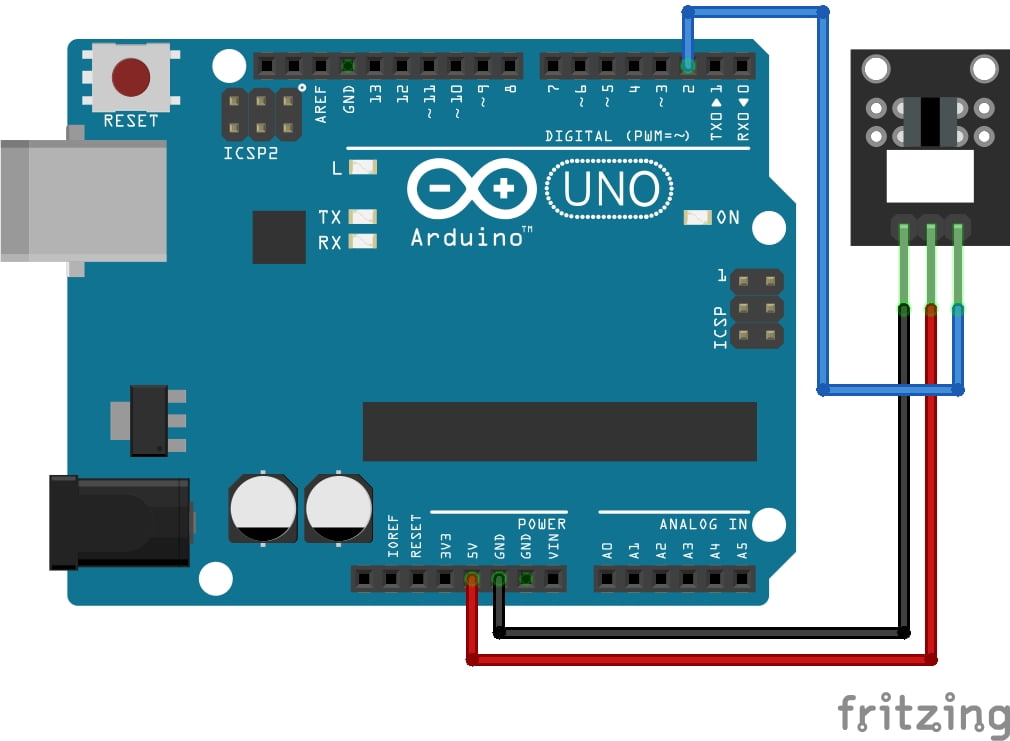
KY-010 Photo Interrupter Module Fritzing Part is created by arduinomodules.info and published under Creative Commons Attribution-ShareAlike 4.0 International license
Arduino Code Example
// Define the pins for the Photo Interrupter
#define interrupterPin 2 // Change this to the pin you're using

volatile int count = 0; // Variable to count interruptions

void setup() {
  pinMode(interrupterPin, INPUT_PULLUP); // Set the sensor pin as input with internal pull-up resistor
  attachInterrupt(digitalPinToInterrupt(interrupterPin), countInterrupts, FALLING); // Attach interrupt to the pin
  Serial.begin(9600); // Initialize serial communication
}

void loop() {
  // Continuously print the count of interruptions
  Serial.print("Count: ");
  Serial.println(count);
  delay(1000); // Delay for readability (adjust as needed)
}

void countInterrupts() {
  count++; // Increment the count when an interruption is detected
}
Breaking Down the Code
Pin Declaration
#define interrupterPin 2: Defines a constant namedinterrupterPinand sets it to digital pin 2, which the Photo Interrupter sensor is connected. Adjust this to match your setup.
Setup Function
pinMode(interrupterPin, INPUT_PULLUP);: Sets the specified pin (interrupterPin) as an input pin with an internal pull-up resistor. This configuration helps in reading the sensor’s state changes.attachInterrupt(digitalPinToInterrupt(interrupterPin), countInterrupts, FALLING);: Attaches an interrupt to the specified pin (interrupterPin). Whenever a falling edge (transition from HIGH to LOW) is detected on this pin, it triggers thecountInterrupts()function.Serial.begin(9600);: Initializes serial communication at a baud rate of 9600 bits per second for monitoring and debugging via the serial monitor.
Loop Function
Serial.print("Count: "); Serial.println(count);: Prints the count of interruptions to the serial monitor. It continuously displays the updated count value.delay(1000);: Adds a 1-second delay between each display of the count for readability. You can adjust this delay as needed.
Interrupt Function
void countInterrupts(): This function serves as the Interrupt Service Routine (ISR). It increments thecountvariable whenever an interruption (falling edge) is detected on the interrupter pin.
This code continuously counts and displays the interruptions detected by the Photo Interrupter sensor using the Arduino’s interrupt capability. Adjust and expand upon this code to incorporate the sensor’s interruptions into more elaborate projects, such as object detection or rotational speed measurement.
Testing
To break the light on a photo interrupter, you need to physically obstruct the path of light between the emitter and the receiver. The photo interrupter typically consists of an infrared LED (emitter) and a phototransistor (receiver) separated by a small gap.
Here’s a simple breakdown:
Emitter and Receiver Alignment: Ensure the emitter and receiver components are correctly aligned. They should face each other directly, with an uninterrupted line of sight between them.
Obstruction: Place an object or material within the gap between the emitter and receiver, interrupting the path of the emitted light. This interruption causes the phototransistor to detect a change in light intensity, signaling an interruption event.
Detection: The interruption in the emitted light triggers a change in the sensor’s output signal. This change can be read by the connected Arduino’s digital pin, allowing you to detect the interruption in your code and initiate actions or responses based on this event.
By physically blocking the light path between the emitter and receiver of the photo interrupter, you simulate an interruption event that the sensor can detect. This interruption is then translated into an electronic signal that your Arduino can interpret and act upon in your code.
Applications and Usage Scenarios
Object Detection
Photo interrupter sensors are commonly used in assembly lines and manufacturing processes to detect the presence or absence of objects on a conveyor belt. For instance, in a packaging facility, photo interrupters can be used to ensure that boxes are correctly positioned before sealing.
Position Sensing
These modules can be employed in printers and scanners to determine the position of print heads or scanning elements. When the print head or scanner moves across the paper, interruptions in the light beam indicate the position of the head or scanner relative to the paper.
Rotary Encoders
Photo interrupter sensors can be used in rotary encoders to measure rotational speed and direction. By placing a rotating disc with slots in front of the photo interrupter, interruptions in the light beam correspond to the rotation of the disc, allowing precise measurement of rotational movement.
Security Systems:
Photo interrupter sensors are used in security systems for detecting unauthorized entry. Placing them strategically across doorways or windows enables the system to detect when someone passes through or opens them.
Tachometers:
In machinery and automotive applications, these modules can be used to measure the speed of rotating components such as shafts or wheels. By interrupting the light beam with a slotted wheel attached to the rotating component, the frequency of interruptions can be used to calculate the rotational speed.
Counting Applications
Photo interrupter sensors are utilized in various counting applications, such as in vending machines to count dispensed items or in traffic systems to count passing vehicles.
Gesture Recognition
Theses modules can be incorporated into devices for gesture recognition, such as touchless switches or controls. By interpreting interruptions in the light beam caused by hand gestures, the device can perform actions accordingly.
Barcode Readers
Photo interrupter sensors are essential components in barcode scanners. They help detect the start and end of the barcode as the scanner moves across it, enabling accurate reading of the barcode data.
Automation in Robotics
Photo interrupter sensors are often used in robotics for tasks such as line following, obstacle detection, and precise movement control.
DIY Projects
Photo interrupter sensors are popular in hobbyist and DIY projects, such as building automated systems, interactive installations, or simple motion detection alarms.
Conclusion
In this sensors and modules guide, we explained the functionality of the Photo Interrupter sensor, exploring its working principles, and demonstrating how to interface it with an Arduino for practical applications. By the end, you should now have a thorough understanding of how this sensor’s light-based detection capabilities can enhance your projects and pave the way for innovative solutions in motion detection and object counting.
Discover the endless possibilities for Arduino projects with more of our Sensors and Modules guides.

This is very well-explained.
This article is a fantastic resource. Your detailed explanations and practical advice are greatly appreciated.