

Welcome to the World of Sensors and Modules with Arduino!
The Obstacle Avoidance Sensor Module is a crucial component in robotics, enabling robots to detect and navigate around obstacles in their environment. In this sensors and modules guide, we’ll explore its working principle, key features, applications, and how it can enhance your Arduino projects.
If you’re new to Arduino, why not take a look at our Getting Started with Arduino guides. These guides are designed for beginners to learn the fundamental basics of Arduino programming.
How the Obstacle Avoidance Sensor Works
The obstacle avoidance sensor emits infrared light pulses and measures the time it takes for them to reflect off objects. By analyzing the reflected infrared signals, the module can determine the distance to any detected obstacles.
Features and Specifications:
- Infrared Sensors: Equipped with infrared (IR) sensors that emit and detect infrared light to detect obstacles in the robot’s path.
- Dual Sensors: Typically includes two IR sensors positioned on opposite sides of the module to provide wide-angle obstacle detection.
- Output: Offers both analog and digital output signals to indicate the distance to detected obstacles.
- Adjustable Sensitivity: Some modules feature adjustable sensitivity controls to fine-tune the detection range based on environmental conditions and obstacle characteristics.
- Operating Voltage: 3.3V ~ 5V.
- Operating Current: 20mA
- Working Temperature: -10 C – +50 C.
- Detection Range: 2cm ~ 40cm.
- Size: 46mm x 17mm.
- Compatibility: This sensor is also compatible with other devices like the Raspberry Pi, ESP32, and ESP8266 etc…
Necessary Equipment:
- Arduino (e.g., Arduino Uno)
- Obstacle Avoidance Sensor Module
- Jumper wires
- Breadboard (optional)
Pin Configuration
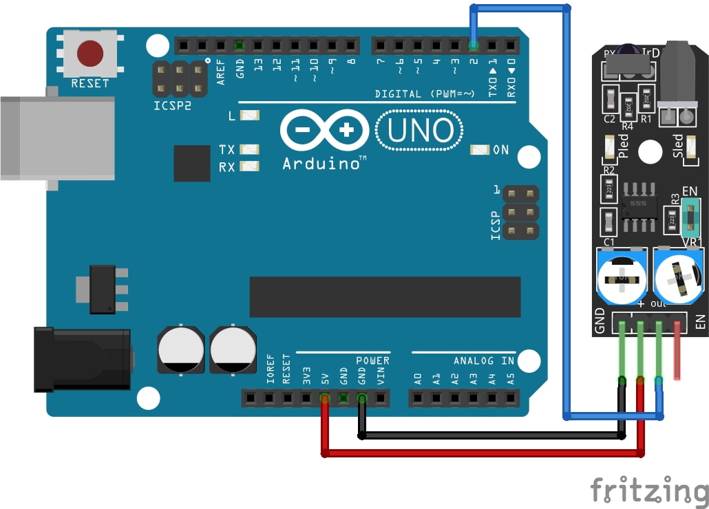
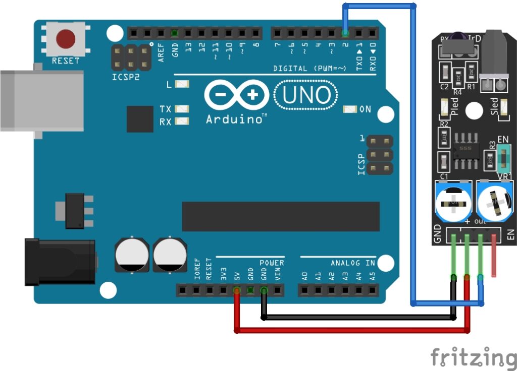
Connecting the Obstacle Avoidance Sensor Module to an Arduino is fairly simple. The connections are as follows:
- GND on the Obstacle Avoidance Sensor Module to GND on the Arduino.
- + on the Obstacle Avoidance Sensor Module to 5V on the Arduino.
- OUT on the Obstacle Avoidance Sensor Module to Digital Pin 2 on the Arduino.
Pin labels may vary.
KY-032 IR Obstacle Avoidance Sensor Module Fritzing Part is created by arduinomodules.info and published under Creative Commons Attribution-ShareAlike 4.0 International license
Arduino Code Example
// Define signal pin.
const int obstacleSignalPin = 2;

void setup() {
  // Initialize serial communication for debugging.
  Serial.begin(9600);

  // Set signal pin as input.
  pinMode(obstacleSignalPin, INPUT);
}

void loop() {
  // Read sensor value.
  int obstacleValue = digitalRead(obstacleSignalPin);

  // Add logic for obstacle avoidance based on sensor reading.
  if (obstacleValue == HIGH){
    // Print sensor value.
    Serial.println("No Obstacle Detected: ");
  }else{
    Serial.println("Obstacle Detected: ");
    // Implement control algorithm to steer the robot away from obstacles.
  }
  delay(100); // Add a short delay for stability.
}
Breaking Down the Code
Definition of Signal Pin
- Defines a constant integer variable to represent the digital signal pin connected to the obstacle avoidance sensor module.
Setup Function
- Initializes serial communication at a specified baud rate for debugging purposes.
- Configures the signal pin as an input pin to receive digital signals from the obstacle avoidance sensor module.
Loop Function
- Reads the digital signal from the signal pin and stores it in a variable.
- Implements conditional logic to determine if an obstacle is detected based on the sensor reading.
- Prints corresponding messages to the Serial Monitor indicating the presence or absence of obstacles.
- Optionally, you can include further logic within the loop to control the robot’s movements based on obstacle detection.
- Adds a short delay for stability to prevent rapid readings and ensure smooth operation of the program.
This code structure allows for continuous monitoring of the obstacle avoidance sensor module’s output signal, providing feedback on obstacle detection. Adjustments or additions to the logic within the code can be made to customize the behavior in response to obstacle detection.
Sensitivity Adjustment
The two trim pots (trimmer potentiometers) on the obstacle avoidance sensor module are typically used for sensitivity adjustment and offset calibration. Here’s how they are commonly utilized:
Sensitivity Adjustment: One of the trim pots is dedicated to adjusting the sensitivity of the obstacle detection system. By turning this trim potentiometer, you can fine-tune the detection range of the sensor, allowing it to detect obstacles at different distances more accurately. Increasing the sensitivity makes the sensor more responsive to obstacles, while decreasing it reduces false detections and improves stability.
Offset Calibration: The other trim potentiometer is often used for offset calibration or threshold adjustment. This trim pot enables you to set a reference point or baseline for the sensor’s output signal. By adjusting the offset, you can establish the threshold at which the sensor considers an object to be an obstacle. This calibration ensures that the sensor operates reliably in various environmental conditions and effectively distinguishes between obstacles and background noise.
Overall, the trim pots provide a means of fine-tuning the sensor’s performance to suit application requirements. Adjusting sensitivity and offset can optimize the sensor’s detection capabilities, minimize false alarms, and enhance the reliability of obstacle detection.
Applications and Usage Scenarios
Obstacle Avoidance Robots
Essential for building robots capable of autonomously navigating cluttered environments while avoiding collisions with obstacles.
Automated Guided Vehicles (AGVs)
Used in industrial settings to guide AGVs safely along designated routes and avoid collisions with equipment or obstacles.
Security Systems
Integrated into security systems to detect and alert operators of intrusions or obstacles in restricted areas.
Smart Home Appliances
Employed in smart home appliances, such as robotic vacuum cleaners, to avoid obstacles and navigate efficiently within indoor spaces.
Conclusion
In this sensors and modules guide, we explained the functionality of the Obstacle Avoidance Sensor, exploring its working principles, and demonstrating how to interface it with an Arduino for practical applications. The obstacle avoidance sensor module plays a crucial role in enabling robots to navigate safely in complex environments by detecting and avoiding obstacles. With its infrared sensors, adjustable sensitivity, and compact design, this module offers a versatile solution for obstacle detection and collision avoidance in a wide range of robotics and automation applications. By integrating the obstacle avoidance sensor module into your Arduino projects, you can enhance the capabilities of your robots and create intelligent systems capable of navigating dynamically changing environments with ease and efficiency.
Discover the endless possibilities for Arduino projects with more of our Sensors and Modules guides.
Thanks for magnificent info I was looking for this information for my mission.
Thank you for this informative and engaging article. The examples you’ve provided make it much easier to understand the concepts you’re discussing.