


Welcome to the World of Sensors and Modules with Arduino!
The GY-521 sensor module, commonly known as the MPU-6050 or MPU-6500, is a versatile component that integrates a gyroscope and an accelerometer into a single package. It is widely used in projects requiring motion sensing, orientation tracking, gesture recognition, and stabilization. The MPU-6500 is an upgraded version of the MPU-6050, offering additional features and improved performance, but this guide is appropriate for both models. In this sensors and modules guide, we’ll explore its working principle, key features, applications, and how it can enhance your Arduino projects.
If you’re new to Arduino, why not take a look at our Getting Started with Arduino guides. These guides are designed for beginners to learn the fundamental basics of Arduino programming.
How the GY-521 Sensor Works
The GY-521 sensor module utilizes MEMS (Micro-Electro-Mechanical Systems) technology to sense changes in orientation and acceleration. The gyroscope measures angular velocity, while the accelerometer measures linear acceleration. By combining the data from both sensors, the module provides comprehensive motion tracking capabilities.
What is a Gyroscope and Accelerometer?
Gyroscope: A gyroscope is a sensor that measures the rate of rotation or angular velocity around one or more axes. It detects changes in orientation or angular movement, providing data on how fast an object is rotating or changing its orientation in space. In the MPU-6050 module, the gyroscope component measures rotational motion along the X, Y, and Z axes, providing data on pitch, roll, and yaw movements.
Accelerometer: An accelerometer is a sensor that measures proper acceleration, which is the acceleration experienced relative to free fall. It detects changes in linear acceleration, including both static acceleration (such as gravity) and dynamic acceleration (such as movement or vibration). In the MPU-6500 module, the accelerometer component measures linear acceleration along the X, Y, and Z axes, providing data on changes in velocity or movement along these axes.
Features and Specifications:
- Operating Voltage: 3.3 ~ 5V.
- Gyroscope Range: ±250, ±500, ±1000, ±2000 dps.
- Accelerometer Range: ±2g, ±4g, ±8g, ±16g.
- Processor: Digital Motion Processor (DMP) for motion processing and sensor fusion.
- Output: I2C and SPI communication.
- Compatibility: This sensor is also compatible with other devices like the Raspberry Pi, ESP32, and ESP8266 etc…
Necessary Equipment:
- Arduino (e.g., Arduino Uno)
- GY-521 sensor module
- Jumper wires
- Breadboard (optional)
Pin Configuration
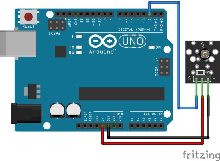
Connecting the GY-521 Sensor Module to an Arduino is fairly simple. The connections are as follows:
- VCC on the MPU-6500 to 5V on the Arduino.
- GND on the MPU-6500 to GND on the Arduino.
- SCL on the MPU-6500 to analog pin A5 on the Arduino.
- SDA on the MPU-6500 to analog pin A4 on the Arduino.
The Extra Pins
This module typically doesn’t require all available connections for basic functionality with an Arduino. Here’s a breakdown of those additional pins:
- EDA or XDA (External Drive Accelerometer): This pin is used to provide an external clock signal to synchronize the accelerometer’s sampling. It’s usually left unconnected when using the MPU-6500 with an Arduino.
- ECL or XCL (External Clock): Similar to EDA, this pin allows for an external clock source for the entire chip. It’s typically not needed for basic usage and left unconnected.
- ADO (Address Select): This pin allows you to select the I2C address of the MPU-6500. If left unconnected, it typically sets the address to the default value (0x68 or 0x69, depending on the logic level of the AD0 pin).
- INT (Interrupt): This pin can be connected to an interrupt pin on the Arduino if you want to use interrupts for motion detection or other purposes. It’s optional for basic functionality.
- NCS (Not Chip Select): This pin is not typically used with the MPU-6500 and can be left unconnected.
- Fsync (Frame Synchronization): This pin is used for synchronization in certain applications but is not required for basic functionality with an Arduino.
For most Arduino projects, you’ll only need to connect VCC, GND, SDA, and SCL pins of the MPU-6500 to the corresponding pins on the Arduino. The INT pin can also be connected if you plan to use interrupts for motion detection or other purposes. The other pins can generally be left unconnected.
Pin labels may vary.

Installing the MPU-6050 Library
Controlling the GY-521 sensor module requires the MPU-6050 library. To install the MPU-6050 library in your Arduino IDE, follow these simple steps:
- Open your Arduino IDE.
- Go to the “Sketch” menu.
- Choose “Include Library” > “Manage Libraries…”.
- In the Library Manager window, type “MPU6050” into the search bar.
- Press Enter, and you should see the MPU6050 library by Electronic Cats.
- Click the “Install” button.
- Once the installation is complete, close the Library Manager.
Arduino Code Example
#include <Wire.h>
#include <MPU6050.h>

MPU6050 mpu;

void setup() {
  Serial.begin(9600);

  Wire.begin();
  mpu.initialize();
}

void loop() {
  int16_t ax, ay, az, gx, gy, gz;

  // Read accelerometer and gyroscope data
  mpu.getMotion6(&ax, &ay, &az, &gx, &gy, &gz);

  // Print accelerometer data
  Serial.print("Accelerometer (mg): ");
  Serial.print(ax); Serial.print(", ");
  Serial.print(ay); Serial.print(", ");
  Serial.println(az);

  // Print gyroscope data
  Serial.print("Gyroscope (°/s): ");
  Serial.print(gx); Serial.print(", ");
  Serial.print(gy); Serial.print(", ");
  Serial.println(gz);

  // Determine the direction of movement based on accelerometer data
  if (ay > 8000) {
    Serial.println("Moving Upwards");
  } else if (ay < -8000) { Serial.println("Moving Downwards"); } else if (ax > 8000) {
    Serial.println("Moving Right");
  } else if (ax < -8000) {
    Serial.println("Moving Left");
  } else {
    Serial.println("No Significant Movement");
  }

  delay(100); // Delay for stability
}
Breaking Down the Code
Including Libraries
- The code includes two libraries:
Wire.hfor I2C communication andMPU6050.hfor interfacing with the MPU-6050 or MPU-6500 sensor modules.
Initializing MPU6050 Object
- An object of type
MPU6050namedmpuis declared. This object is used to interact with the MPU-6050 or MPU-6500 sensor modules.
Setup Function
- Serial communication is initiated at a baud rate of 9600 baud.
- I2C communication is initialized with
Wire.begin(). - The MPU-6500 sensor module is initialized using
mpu.initialize().
Loop Function:
- Variables
ax,ay,az,gx,gy, andgzare declared to store accelerometer and gyroscope data. - Accelerometer and gyroscope data are read using
mpu.getMotion6()function. - Accelerometer data (x, y, z) and gyroscope data (x, y, z) are printed to the Serial Monitor.
- The direction of movement is determined based on accelerometer data:
- If the
ayvalue is greater than 8000, it indicates upward movement. - If the
ayvalue is less than -8000, it indicates downward movement. - If the
axvalue is greater than 8000, it indicates rightward movement. - If the
axvalue is less than -8000, it indicates leftward movement. - If none of the above conditions are met, it prints “No Significant Movement”.
- If the
- A delay of 100 milliseconds is added for stability.
Applications and Usage Scenarios
Motion Tracking
Use the GY-521 sensor module to track the orientation and movement of objects in 3D space, enabling applications such as virtual reality (VR), robotics, and drone navigation.
Gesture Recognition
Implement gesture recognition algorithms to detect and interpret hand movements for interactive applications, gaming interfaces, or human-computer interaction systems.
Stabilization Systems
Develop stabilization systems for cameras, platforms, or vehicles by using the sensor data to compensate for unwanted motion and maintain a steady orientation.
Activity Monitoring
Monitor human activity patterns, such as walking, running, or cycling, by analyzing the accelerometer data to track steps, measure speed, or estimate calorie expenditure.
Conclusion
In this sensors and modules guide, we explained the functionality of the GY-521 Sensor Module, exploring its working principles, and demonstrating how to interface it with an Arduino for practical applications. The GY-521 sensor module serves as a powerful tool for motion sensing and orientation tracking in Arduino projects. Its integration of gyroscope and accelerometer functionalities provides comprehensive motion data, enabling a wide range of applications from gesture recognition to stabilization systems. By exploring its features, working principles, applications, and usage scenarios, we unlock the potential of the GY-521 module to enhance projects with precise motion control and sensing capabilities.
Discover the endless possibilities for Arduino projects with more of our Sensors and Modules guides.