

Exploring Basic Components with Arduino!
Welcome to Meganano’s series of comprehensive guides on using basic components with Arduino! In this particular guide, we’ll be focusing specifically on resistors, exploring their functions, types, applications, and best practices for integrating them into your Arduino projects.
If you’re new to Arduino, why not take a look at our Getting Started with Arduino guides. These guides are designed for beginners to learn the fundamental basics of Arduino programming.
Introduction to Resistors
What are Resistors?
A resistor is a passive two-terminal electrical component that resists the flow of electric current. It acts as an obstacle to the flow of electrons, impeding the current passing through it. This resistance is measured in ohms (Ω), named after the German physicist Georg Simon Ohm, who formulated Ohm’s Law.
Basic Concept of Resistance
Resistance, measured in ohms, is a property exhibited by materials that oppose the flow of electric current. Think of it as the degree of difficulty that electrons encounter as they move through a material. Some materials, like metals, offer little resistance, allowing electrons to flow easily, while others, like rubber or glass, offer high resistance, impeding electron flow significantly.
Purpose and Role of the Resistor
Resistors serve a multitude of purposes in electronic circuits. Here are some of their key roles:
Current Limiting: A resistor is frequently used to limit the amount of current flowing through a circuit, ensuring that components receive only the necessary amount of current to operate safely.
Voltage Division: By creating voltage dividers, resistors enable the reduction of voltage levels within a circuit, allowing for precise control over voltage levels at various points.
Signal Conditioning: A resistor is often employed in signal processing circuits to modify the amplitude or shape of electrical signals.
Biasing and Gain Control: In amplifier circuits, resistors are used to set bias points and control the gain of the amplifier.
Temperature Sensing: Certain types of resistors, such as thermistors, exhibit a change in resistance with temperature, making them ideal for temperature sensing applications.
In essence, a resistor provides the necessary flexibility and control required to design and manipulate electronic circuits, making them indispensable components in the world of electronics.
Understanding the basics of resistors is crucial for anyone diving into electronics, including Arduino enthusiasts. In the following sections, we’ll delve deeper into the intricacies of resistors, exploring their types, characteristics, and practical applications in Arduino projects.
Understanding Resistance
Resistance is a fundamental property of materials that determines how easily electric current can flow through them. Let’s delve deeper into the concept of resistance and explore its significance in electronic circuits.
Definition of Resistance
Resistance is the measure of how much a material opposes the flow of electric current. It is denoted by the symbol ‘R’ and measured in ohms (Ω). In simple terms, resistance can be thought of as the “friction” that electrons encounter as they move through a material. The higher the resistance, the more difficult it is for electrons to flow.
Factors Affecting Resistance
Several factors influence the resistance of a material:
Material: Different materials have different inherent resistivities, affecting their resistance. For example, metals like copper and aluminum have low resistivities and thus low resistance, whereas insulators like rubber and glass have high resistivities and high resistance.
Length: The longer the path electrons must travel through a material, the higher the resistance. This is because there are more collisions between electrons and atoms along a longer path, impeding the flow of current.
Cross-sectional Area: A larger cross-sectional area allows more electrons to flow through a material, reducing resistance. Conversely, a smaller cross-sectional area restricts electron flow, increasing resistance.
Ohm’s Law
Ohm’s Law, formulated by the German physicist Georg Simon Ohm, describes the relationship between voltage (V), current (I), and resistance (R) in an electrical circuit. It can be expressed mathematically as:
V = I × RWhere:
- V is the voltage across the resistor (measured in volts, V).
- I is the current flowing through the resistor (measured in amperes, A).
- R is the resistance of the resistor (measured in ohms, Ω).
Ohm’s Law is essential for understanding and predicting the behavior of electrical circuits involving resistors.
Applications of Resistance
Resistance finds numerous applications in electronic circuits, including:
Current Limiting: Resistors are commonly used to limit the amount of current flowing through a circuit, preventing damage to components.
Voltage Division: By using resistors in voltage divider circuits, specific voltage levels can be obtained for various components in a circuit.
Temperature Sensing: Certain types of resistors, like thermistors, exhibit changes in resistance with temperature, making them useful for temperature sensing applications.
Understanding resistance is crucial for designing and troubleshooting electronic circuits effectively. In the next section, we’ll explore how resistors are represented and identified using the resistor color code.
Resistor Color Code
The resistor color code is a standardized system used to represent the resistance value of resistors. Understanding how to read resistor values using the color code is essential for identifying and selecting the right resistors for electronic circuits.
Explanation of Resistor Color Bands
A resistor typically has four or five color bands painted or printed onto its body. Each color band represents a digit or multiplier that, when combined, denote the resistance value of the resistor. Here’s how the color bands are interpreted:
- First Band (1st Digit): Represents the first digit of the resistance value.
- Second Band (2nd Digit): Represents the second digit of the resistance value.
- Third Band (Multiplier): Indicates the multiplier by which the first two digits are multiplied to obtain the resistance value.
- Fourth Band (Tolerance): Specifies the tolerance of the resistor, i.e., the permissible variation in resistance from the nominal value.
How to Read Resistor Values Using the Color Code
To read the resistance value of a resistor using the color code, follow these steps:
- Identify the First and Second Bands: Determine the colors of the first and second bands and their corresponding digit values using a color code chart.
- Determine the Multiplier: Identify the color of the third band to determine the multiplier value.
- Calculate the Resistance Value: Combine the digits from the first and second bands and multiply the result by the multiplier value.
- Check the Tolerance: If the resistor has a fourth band, check its color to determine the tolerance.
Examples and Practice Exercises
Let’s take a look at some examples to illustrate how to read resistor values using the color code:
- Example 1: A resistor with color bands Brown-Black-Red-Gold represents a resistance value of 1000 ohms (10 × 10^2 ohms) with a tolerance of ±5%.
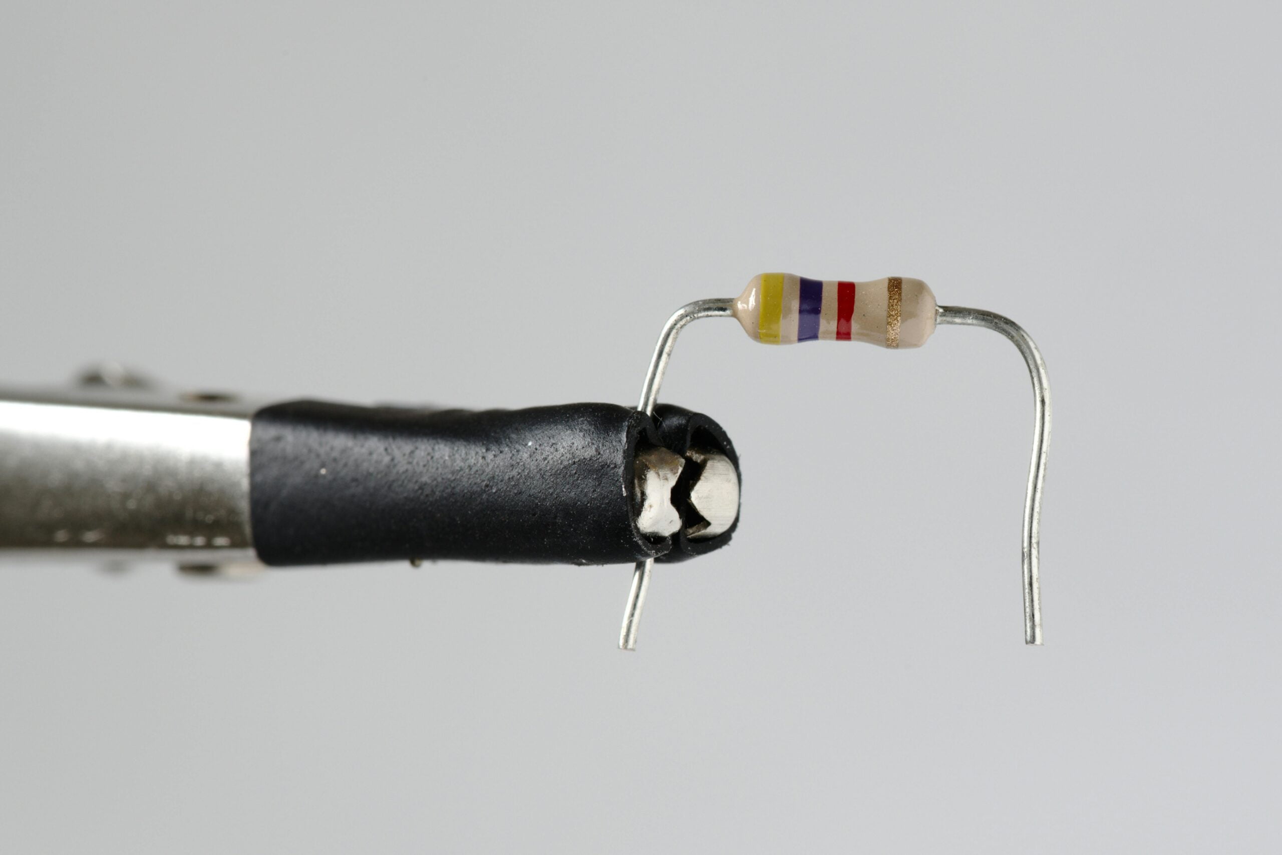
- Example 2: A resistor with color bands Yellow-Violet-Brown-Silver represents a resistance value of 470 ohms (47 × 10^1 ohms) with a tolerance of ±10%.
Practice decoding resistor values using the color code to reinforce your understanding and proficiency.
Tips for Decoding Resistor Values
- Use a color code chart or online calculator to quickly determine the resistance value.
- Pay attention to the order of the bands and their position on the resistor.
- Double-check your calculations and interpretation to avoid errors.
Mastering the resistor color code is a valuable skill that will greatly assist you in selecting and utilizing resistors effectively in your electronic projects. In the next section, we’ll explore the different types of resistors commonly used in circuits.
Types of Resistors
The resistor comes in various different types, each with its own characteristics and applications. Understanding the differences between these types can help you choose the most suitable resistor for your electronic circuit.
Overview of Different Resistor Types:
Carbon Film Resistors
- The carbon film resistor is among the most common type of resistor, and the ones you will find in your Arduino kit. They consist of a ceramic rod coated with a thin layer of carbon film, onto which the resistance pattern is printed.
- They offer good stability, accuracy, and temperature coefficient, making them suitable for general-purpose applications.
Metal Film Resistors
- Similar to carbon film resistors, the metal film resistor uses a thin layer of metal, typically nickel-chromium (Nichrome), as the resistive element.
- The metal film resistor offers higher precision, lower noise, and better temperature stability compared to the carbon film resistor, making them suitable for precision applications and audio circuits.
Wirewound Resistors
- The wirewound resistor is constructed by winding a resistive wire, typically made of nichrome or a similar alloy, around a ceramic or fiberglass core.
- They offer high power handling capability and low inductance, making them suitable for high-power and high-frequency applications, such as power supplies and amplifiers.
Thick Film Resistors
- Thick film resistors are manufactured by depositing a thick film of resistive material, such as ruthenium oxide or tantalum nitride, onto a ceramic substrate.
- These resistors offer high power dissipation, excellent stability, and low cost, making them suitable for a wide range of applications, including automotive electronics and industrial controls.
Surface Mount Resistors (SMD)
- Surface mount resistors are compact resistors designed for surface mount technology (SMT) assembly onto printed circuit boards (PCBs).
- They come in various package sizes and shapes, offering space-saving advantages and enabling high-density circuit designs.
Advantages and Disadvantages:
Carbon Film and Metal Film Resistors
- Advantages: Low cost, good stability, and wide availability.
- Disadvantages: Limited precision compared to other types, and susceptibility to noise.
Wirewound Resistors
- Advantages: High power handling capability, low inductance, and excellent stability.
- Disadvantages: Higher cost and larger size compared to other types.
Thick Film Resistors
- Advantages: High power dissipation, excellent stability, and low cost.
- Disadvantages: Limited precision compared to metal film resistors.
Recommendations for Selection
When selecting a resistor type for your application, consider factors such as precision requirements, power handling capability, size constraints, and cost. Choose the type that best meets your specific needs while staying within your budget.
Understanding the characteristics and applications of different resistor types will enable you to make informed decisions when designing electronic circuits. In the next section, we’ll explore resistor ratings and their significance in circuit design.
Resistor Ratings
Resistors are rated based on various parameters that determine their performance and reliability in electronic circuits. Understanding resistor ratings is essential for selecting the right resistor for your application and ensuring its proper operation within the circuit.
Power Rating (Wattage)
The power rating of a resistor specifies the maximum amount of power it can dissipate without overheating or sustaining damage. It is denoted in watts (W). Exceeding the power rating can cause the resistor to overheat, leading to drift in resistance value or even physical damage.
Derating Curve
The power dissipation capability of a resistor is affected by factors such as ambient temperature, airflow, and mounting conditions. A derating curve graphically represents how the power rating of a resistor decreases as the ambient temperature increases. Operating a resistor above its rated power in elevated temperatures can lead to accelerated aging and premature failure.
Importance of Power Rating in Circuit Design
When selecting a resistor for your circuit, ensure that the power rating of the resistor exceeds the maximum power dissipation expected in the application. Consider factors such as voltage across the resistor and the current passing through it to calculate the power dissipation using the formula:
P = V × IWhere:
- P is the power dissipation (in watts).
- V is the voltage across the resistor (in volts).
- I is the current passing through the resistor (in amperes).
Example:
Consider a resistor with a power rating of 0.25 watts. If the voltage across the resistor is 12 volts and the current passing through it is 20 milliamps (0.02 amperes), the power dissipation would be:
P = 12 × 0.02 = 0.24 wattsIn this case, the power dissipation is within the rated power of the resistor.
Tips for Proper Resistor Usage:
- Choose a resistor with a power rating higher than the calculated power dissipation to provide a safety margin.
- Ensure proper airflow and heat sinking for high-power resistors to dissipate heat effectively.
- Use multiple resistors in parallel to increase the total power handling capability if needed.
Understanding resistor ratings, particularly the power rating, is crucial for designing reliable and robust electronic circuits. In the next section, we’ll explore resistor networks and their applications in circuit design.
Resistor Network
Resistor networks, also known as resistor arrays, are configurations of multiple resistors integrated into a single package. These networks offer several advantages over individual resistors, including space-saving, simplified circuit layout, and improved accuracy in matching resistor values.
Explanation of Resistor Networks
Resistor networks consist of several resistors connected together within a single package. They are available in various configurations, such as isolated, bussed, and dual in-line packages (DIP). In isolated networks, each resistor has its own terminal, while in bussed networks, one terminal is shared among multiple resistors.
Common Configurations
Voltage Divider Networks:
- Voltage divider networks consist of two resistors connected in series, dividing the input voltage into a fraction of the original voltage. They are commonly used in analog circuits for level shifting and signal conditioning.
Pull-Up and Pull-Down Networks:
- Pull-up and pull-down resistor networks consist of resistors connected between a signal line and the supply voltage (pull-up) or ground (pull-down). They are frequently used in digital circuits for input and output signal conditioning, as well as for biasing purposes.
Termination Networks:
- Termination networks consist of resistors placed at the ends of transmission lines to match impedance and minimize signal reflections in high-speed digital communication systems.
Advantages of Resistor Networks
Space-Saving: Resistor networks offer a compact solution by integrating multiple resistors into a single package, saving valuable board space in densely populated circuits.
Improved Matching: Resistor networks provide better matching between resistor values compared to individual resistors, ensuring higher accuracy and consistency in circuit performance.
Simplified Assembly: Integrating multiple resistors into a single package simplifies assembly and reduces the number of solder joints, enhancing reliability and manufacturability.
Applications
Resistor networks find applications in various electronic circuits, including:
- Analog and digital signal conditioning circuits.
- Voltage dividers for sensor interfacing.
- Pull-up and pull-down networks in microcontroller-based systems.
- Impedance matching and termination in high-speed data transmission.
Considerations
When selecting a resistor network for your application, consider factors such as the required resistor values, tolerance, and package type. Ensure that the chosen network meets the specifications and performance requirements of your circuit.
Understanding the capabilities and applications of resistor networks expands your options for designing efficient and compact electronic circuits. In the next section, we’ll explore practical examples of resistors in Arduino circuits.
Resistor in Circuit Design
Resistors play a vital role in circuit design, serving various functions such as current limiting, voltage division, signal conditioning, and biasing. Understanding how to incorporate resistors effectively in Arduino circuits is essential for creating functional and reliable electronic projects.
Current Limiting with Resistors
Resistors are commonly used to limit the amount of current flowing through a circuit, protecting components from damage due to excessive current. For example, in LED circuits, a resistor is connected in series with the LED to limit the current flowing through it to a safe value, preventing the LED from burning out.
Voltage Division Using Resistors
Resistors are essential components in voltage divider circuits, which divide a voltage into a fraction of its original value. Voltage dividers are widely used in sensor interfacing, analog signal processing, and setting reference voltages. By carefully selecting resistor values, precise voltage levels can be obtained for specific applications.
Pull-Up and Pull-Down Resistors
The Pull-up and pull-down resistors are used in digital circuits to ensure that input signals have a defined voltage level when not actively driven by a signal source. Pull-up resistors are connected between the signal line and the supply voltage (usually VCC), while pull-down resistors are connected between the signal line and ground. These resistors prevent floating inputs and ensure reliable signal detection in microcontroller-based systems like Arduino.
Biasing and Gain Control
Resistors are employed in amplifier circuits for biasing and gain control purposes. Biasing resistors set the operating point of the amplifier, ensuring proper transistor or op-amp operation. Additionally, feedback resistors determine the gain of the amplifier, controlling the amplification factor of the circuit.
Voltage Reference and Temperature Sensing
Resistors are also used in voltage reference circuits and temperature sensing applications. Precision resistors with low temperature coefficients are employed to generate stable reference voltages, critical for accurate analog-to-digital conversions in Arduino projects. Thermistors, which are temperature-sensitive resistors, can be used for temperature measurement and control in various applications.
Practical Examples
- LED Current Limiting: Connect a resistor in series with an LED to limit the current flowing through it.
- Analog Sensor Interfacing: Use a voltage divider circuit to interface analog sensors with Arduino analog input pins.
- Pull-Up Resistor for Button Input: Connect a pull-up resistor between a push-button and VCC to ensure reliable input detection.
- Op-Amp Biasing: Set the bias point of an operational amplifier using biasing resistors in non-inverting amplifier configurations.
Resistors are versatile components that play a crucial role in Arduino circuit design. By understanding their functions and applications, you can effectively incorporate resistors into your projects to achieve desired circuit behavior and performance.
In the next section, we’ll explore common mistakes and troubleshooting techniques related to resistors in Arduino circuits.
Practical Tips
When working with resistors in Arduino circuits, it’s essential to follow best practices to ensure proper functionality, reliability, and safety. Here are some practical tips to consider:
How to Identify a Resistor
- Read the color bands: Use a color code chart to decode the resistance value indicated by the color bands on the resistor.
- Use a multimeter: Measure the resistance value using a multimeter’s resistance measurement function.
How to Solder Resistors Properly
- Use the right soldering iron: Choose a soldering iron with an appropriate wattage for the task.
- Ensure clean joints: Clean the soldering iron tip and the resistor leads before soldering to achieve good solder joints.
- Apply solder correctly: Heat the joint with the soldering iron and apply solder to form a shiny, smooth solder connection.
Best Practices for Handling and Storing Resistors
- Handle with care: Avoid bending or damaging the resistor leads, as it can affect their electrical properties.
- Store properly: Keep resistors in a dry, dust-free environment to prevent corrosion and damage.
Calculate Resistor Values for Circuits
- Use Ohm’s Law: Calculate the resistance value needed for current limiting or voltage division using Ohm’s Law (V = IR).
- Consider tolerance: Factor in the tolerance of the resistor when calculating resistor values for precise applications.
Test Resistors Before Use
- Measure resistance: Use a multimeter to measure the resistance of resistors before incorporating them into circuits.
- Check tolerance: Verify that the measured resistance falls within the specified tolerance range of the resistor.
Use Resistor Arrays for Compact Designs
- Consider resistor arrays: Use resistor networks or arrays to save space and simplify circuit layout, especially in densely populated PCB designs.
- Choose the right configuration: Select resistor array configurations (isolated, bussed, etc.) based on the specific requirements of your circuit.
Document Resistor Values in Circuits
- Label resistors: Clearly label resistors in circuit diagrams or on PCBs to ensure easy identification and troubleshooting.
- Keep a record: Maintain a record of resistor values used in your circuits for future reference and replication.
Consider Temperature Effects
- Account for temperature coefficient: Choose resistors with low temperature coefficients (TCR) for applications sensitive to temperature changes.
- Consider ambient temperature: Take into account the operating temperature range of the environment when selecting resistors for long-term reliability.
By following these practical tips, you can effectively work with resistors in Arduino circuits, ensuring optimal performance and longevity of your electronic projects.
In the next section, we’ll explore common mistakes and troubleshooting techniques related to resistors in Arduino circuits.
Common Mistakes and Troubleshooting
While working with resistors in Arduino circuits, beginners often encounter common mistakes that can lead to circuit malfunctions or performance issues. Understanding these mistakes and knowing how to troubleshoot them is essential for successful project development. Here are some common mistakes and troubleshooting techniques:
Incorrect Resistor Value
- Mistake: Using the wrong resistor value can lead to incorrect circuit behavior, such as dim LEDs or incorrect voltage levels.
- Troubleshooting:
- Double-check resistor values: Ensure that the resistor values used in the circuit match the design requirements.
- Measure resistor values: Use a multimeter to measure the resistance of resistors and verify they match their specified values.
Poor Soldering Connections
- Mistake: Poor soldering connections can result in unreliable electrical connections, leading to intermittent operation or circuit failure.
- Troubleshooting:
- Inspect solder joints: Visually inspect solder joints for proper wetting and fillets.
- Re-solder connections: If necessary, re-solder suspect joints to ensure good electrical and mechanical connections.
Overheating Resistors
- Mistake: Exceeding the power rating of resistors can cause them to overheat, leading to drift in resistance value or physical damage.
- Troubleshooting:
- Use higher power resistors: Select resistors with higher power ratings or distribute the power dissipation among multiple resistors if needed.
- Improve heat dissipation: Enhance airflow or add heat sinks to dissipate heat effectively.
Incorrect Wiring or Circuit Layout
- Mistake: Incorrect wiring or circuit layout can result in short circuits, open circuits, or unintended signal paths.
- Troubleshooting:
- Review circuit schematic: Double-check the circuit schematic against the physical wiring to identify any discrepancies.
- Use breadboarding techniques: Utilize breadboards for prototyping to easily rearrange and troubleshoot circuit connections.
Forgetting Pull-Up or Pull-Down Resistors
- Mistake: Forgetting to include pull-up or pull-down resistors in digital circuits can lead to unreliable signal detection or floating inputs.
- Troubleshooting:
- Add pull-up or pull-down resistors: Include appropriate pull-up or pull-down resistors in digital circuits to ensure defined signal levels when inputs are not actively driven.
Using the Wrong Type of Resistor
- Mistake: Using the wrong type of resistor for a specific application can result in performance issues or circuit instability.
- Troubleshooting:
- Select appropriate resistor types: Choose resistor types based on the requirements of the circuit, considering factors such as precision, power handling, and temperature stability.
Ignoring Temperature Effects
- Mistake: Ignoring temperature effects can lead to variations in resistor values and circuit performance, especially in applications with wide temperature ranges.
- Troubleshooting:
- Consider temperature coefficients: Choose resistors with low temperature coefficients (TCR) for applications sensitive to temperature changes.
- Ensure proper thermal management: Provide adequate ventilation or heat sinking to maintain stable operating temperatures for resistors.
By being aware of these common mistakes and employing effective troubleshooting techniques, you can identify and resolve issues encountered when working with resistors in Arduino circuits, ensuring successful project execution.
In the next section, we’ll provide additional resources and further reading materials for expanding your knowledge of resistors and electronics.
Resources and Further Reading
Expanding your knowledge of resistors and electronics is crucial for mastering Arduino projects and circuit design. Here are some recommended resources and further reading materials to deepen your understanding:
Books
“Practical Electronics for Inventors” by Paul Scherz and Simon Monk – A comprehensive guide covering electronics fundamentals, including resistors, capacitors, and semiconductors.
“The Art of Electronics” by Paul Horowitz and Winfield Hill – Widely regarded as a classic in the field, this book provides in-depth coverage of electronic circuit design, including practical examples and applications.
Online Courses and Tutorials
Arduino official website – Explore the Arduino website for tutorials, project ideas, and documentation on using resistors and other electronic components in Arduino projects.
YouTube tutorials – Search for educational channels specializing in electronics and Arduino tutorials, offering step-by-step guides on using resistors and troubleshooting common issues.
Websites and Forums
Electronics Stack Exchange – A community-driven Q&A platform where you can ask questions and seek advice on electronics-related topics, including resistor selection, circuit design, and troubleshooting.
Adafruit Learning System – A wealth of tutorials, guides, and project ideas for makers and electronics enthusiasts, covering a wide range of topics, including Arduino, sensors, and circuit design.
Online Tools and Calculators
Resistor Color Code Calculator – Use online tools to quickly decode the resistance value of resistors based on their color bands, saving time and minimizing errors.
Ohm’s Law Calculator – Calculate voltage, current, resistance, and power in electronic circuits using Ohm’s Law equations, simplifying circuit design and analysis.
Arduino Forums and Communities
Arduino Forum – Engage with the Arduino community to seek advice, share projects, and troubleshoot issues related to using resistors and other components in Arduino circuits.
Reddit Arduino Community – Join the Arduino subreddit to participate in discussions, ask questions, and learn from fellow Arduino enthusiasts about resistor applications and circuit design.
Manufacturer Datasheets
Refer to datasheets provided by resistor manufacturers for detailed specifications, application notes, and recommended usage guidelines for specific resistor products.
Conclusion
Congratulations! You’ve completed this “Basic Components with Arduino” guide on resistors. Throughout this journey, we’ve explored the fundamental principles of resistors, their various types, applications, and best practices for incorporating them into your projects. From understanding the resistor color code to selecting the right resistor type, from current limiting to voltage division, you’ve gained valuable insights and practical knowledge to design, build, and troubleshoot Arduino circuits with confidence.
Remember, experimentation is key to mastery. Don’t hesitate to explore, tinker, and push the boundaries of what’s possible with resistors and Arduino. Embrace challenges, learn from mistakes, and celebrate every success along the way.
To explore even more of our basic components with Arduino guides, visit Basic Components with Arduino for a wealth of resources and inspiration to fuel your Arduino projects.
Elegoo Kits
In our opinion Elegoo provide the best quality kits for creating Arduino projects. They come complete with an Arduino microcontroller board and many components, sensors, and modules to help you create amazing projects. Meganano highly recommends these kits for anyone who wants to learn or already enjoys programming with Arduino!
Meganano is a participant in the Amazon Services LLC Associates Program, an affiliate advertising program designed to provide a means for us to earn fees by linking to Amazon.co.uk and affiliated sites. This means that when you click on product links and make a purchase on Amazon, we may receive a small commission at no extra cost to you. We only recommend products that we genuinely believe in, and think will be of value to our readers. Your support through these links helps us continue to provide quality content to you. Meganano Thanks you for your support!
