
How to Capture GPS Data and Record it too an SD Card
In this guide we are going to use the GPS module with an Arduino and then send the captured data to an SD Card in an SD Card Module. So, whether you’re a hobbyist, a tech enthusiast, or a DIY adventurer, this guide will equip you with the skills to track and log your journeys with precision and ease.
Let's Build!
Logging GPS data with the SD-card module
If you need to learn how to interface the SD card module with Arduino, please read our guide here: The SD Card Module for Arduino Projects
We are going to build a GPS data logger complete with status lights to inform us what the device is currently doing. The LEDs will tell you the state the Arduino GPS Logger is in, this can be helpful to see if its working or not while on the move, the last thing you want is to be out all-day logging data to come home and find nothing was logged.
Components:
You may need to install any missing libraries, to learn how to do this you can follow our guide here: How to Install Arduino Libraries
The Code:
When working with an SD card module and Arduino, you’ll typically use libraries like the SD.h library to interact with the SD card, making it relatively straightforward to implement data logging and file storage functionality in your projects. If you need to learn how, you can follow our guide here: How to Install Arduino Libraries
#include <TinyGPS++.h>
#include <SoftwareSerial.h>
#include <SPI.h>
#include <SD.h>

int rec = 7; //displays when data is being logged
int waiting = 6; //displays while connecting
int noSD = 5; //displays if bad SD
unsigned long lastTime = 0;
int intervalTime = 10000;
int chipSelect = 10;
int RXpin=3;
int TXpin=4;
SoftwareSerial gpsConnection(RXpin,TXpin);
TinyGPSPlus gps;
String logFileName = "";

void initializeSD() {
  int i = 1;
  logFileName = "gps-log1.txt";
  while (SD.exists(logFileName)) {
    i++; logFileName = "gps-log" + String(i) + ".txt";
  }
  File logFile = SD.open(logFileName, FILE_WRITE);
  if (logFile) {
    logFile.println("myGPS");
    logFile.close();
  }
}

void setup() {
  Serial.begin(9600);
  gpsConnection.begin(9600);
  pinMode(rec,OUTPUT);
  pinMode(waiting,OUTPUT);
  pinMode(noSD,OUTPUT);
  if (!SD.begin(chipSelect)) {
    digitalWrite(noSD,HIGH);
    while (!SD.begin(chipSelect));
  }
  initializeSD();
  digitalWrite(noSD,LOW);
  delay(500);
}

void loop() {
  File logFile = SD.open(logFileName, FILE_WRITE);
  while(gpsConnection.available()){
    gps.encode(gpsConnection.read());
    digitalWrite(waiting,HIGH);
    digitalWrite(rec,LOW);
  }
  if(gps.location.isUpdated()){
    unsigned long currentTime = millis();
    if((currentTime - lastTime) >= (intervalTime)){
      lastTime = currentTime;
      digitalWrite(rec,HIGH);
      digitalWrite(waiting,LOW);
      logFile.println("");
      logFile.println("********************");
      logFile.println("");
      logFile.print(gps.date.day());
      Serial.println(gps.date.day());
      logFile.print("/");
      logFile.print(gps.date.month());
      logFile.print("/");
      logFile.println(gps.date.year());
      logFile.print(gps.time.hour());
      logFile.print(":");
      logFile.print(gps.time.minute());
      logFile.print(":");
      logFile.print(gps.time.second());
      logFile.println(" (24hr)");
      logFile.println("");
      logFile.print("Satellites: ");
      logFile.println(gps.satellites.value());
      logFile.print("Horizontal dilution of precision: ");
      logFile.println(gps.hdop.value());
      logFile.println("");
      logFile.print("Longitude: ");
      logFile.println(gps.location.lng(), 6);
      logFile.print("Latitude: ");
      logFile.println(gps.location.lat(), 6);
      logFile.println("");
      logFile.print("Direction of Travel: ");
      logFile.print(gps.course.deg());
      logFile.println(" degrees");
      logFile.println("Travel Speed:");
      logFile.print(gps.speed.mph());
      logFile.println(" Mph");
      logFile.print(gps.speed.kmph());
      logFile.println(" Km");
      logFile.print(gps.speed.knots());
      logFile.println(" Knots");
      logFile.println("");
      logFile.println("Altitude: ");
      logFile.print(gps.altitude.feet());
      logFile.println(" Feet");
      logFile.print(gps.altitude.meters());
      logFile.println(" Meters");
      logFile.print("");
    }
  }
  logFile.close();
  delay(500);
}
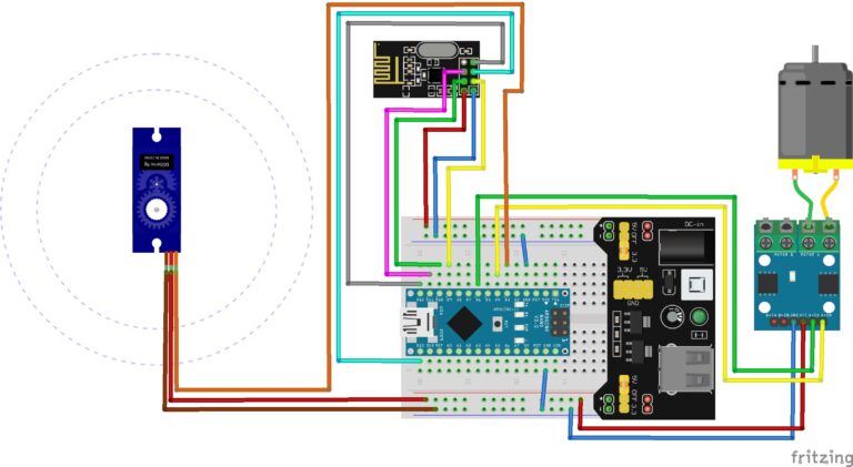
The Circuit:
GPS connections are as follows:
- RX connects to pin 2 on the Arduino.
- TX connects to pin 3 on the Arduino.
- VCC connects to 5v on the Arduino.
- GND connects to GND on the Arduino.
SD Card Module connections are as follows:
- DO to pin 12 on Arduino.
- GND to GND on Arduino.
- SCK to pin 13 on Arduino.
- VCC to 5V on Arduino.
- DI to pin 11 on Arduino.
- CS to pin 10 on Arduino.
LED Connections are as follows:
- Red LED connects to pin 7 on Arduino.
- Yellow LED connects to pin 6 on Arduino.
- Blue LED connects to pin 5 on Arduino.
Don’t forget to use a current limiting resistor for each LED.
Assemble the components in the exact same way as in the image shown below:

Upload the Code:
When everything is assembled go ahead and upload the code. Here is what the LEDs mean:
- Flashing Blue LED means bad SD card or module
- Bold Yellow LED means its waiting, either for a connection or to create next log.
- Flashing Red LED means GPS data is being written.
If you’re stuck on the bold Yellow LED, you need to move your GPS to a better location, maybe hang it higher up, put it next to a window, or take it outside. Once the Red LED begins flashing it has found a connection and GPS data will get written to the SD card.
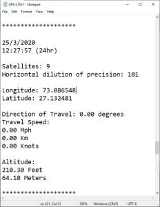
Any returned data is written to a text file created on the SD card and the content should look similar to the image below:
Conclusion
The data you log is more than numbers and coordinates; it’s a record of your experiences, adventures, and discoveries. Your GPS data logger is a gateway to storytelling, analysis, and future innovations.
So, as you embark on your next journey, remember the power you hold in your hands, a tool that not only navigates the physical world but also preserves memories and insights. Share your findings, inspire others, and continue pushing the boundaries of what’s possible with Arduino and GPS technology.
Recommendations:
The Elegoo Super Starter Kit
If you don’t already own any Arduino hardware, we highly recommend this kit as it has everything you need to start programming with Arduino. You can find out more about this kit, including a list of its components here: Elegoo Super Starter Kit
You can find this kit on Amazon here: Elegoo Super Starter Kit
The 0.96-inch Mini-OLED Display
We highly recommend this mini-OLED bundle of five 0.96-inch OLED displays. We have bought these before and they all worked perfectly. You can read more about the mini-OLED here: Mini-OLED
You can find this bundle on Amazon here: OLED Displays
Elegoo Nano (Arduino Compatible)
We have bought these Nano boards many times and can highly recommend them. There are three Nano boards in this pack making them a total bargain for everyone.
You can find this pack on Amazon here: Arduino Nano