Welcome to the World of Sensors and Modules with Arduino!
Introduction to NRF24L01
The NRF24L01 is a popular 2.4GHz radio frequency (RF) transceiver module which works great with Arduino. It’s widely used in wireless communication applications, particularly in low-power and low-cost scenarios like IoT (Internet of Things), remote control systems, and sensor networks. The communication protocol for the NRF24L01 is proprietary to Nordic Semiconductor, the manufacturer of the chip. This is guide is for beginners to help you get to know the NRF24L01 module before embarking on creating your first projects.
Key Features:
- Low Power Consumption: The NRF24L01 module is designed to operate with minimal power consumption, making it suitable for battery-powered applications where power efficiency is crucial.
- Small Form Factor: With its compact size, the NRF24L01 module can be easily integrated into various electronic projects without occupying much space.
- Low Cost: Despite its advanced features, the NRF24L01 module is available at an affordable price point, making it accessible to hobbyists, students, and professionals alike.
- Enhanced Data Rate: The NRF24L01 supports multiple data rates, allowing users to choose the appropriate rate based on their specific application requirements.
- Multi-Channel Operation: It offers multi-channel operation, enabling simultaneous communication between multiple NRF24L01 modules within the same vicinity without interference.
Applications
The NRF24L01 module finds applications in various fields, including:
- Wireless Sensor Networks: Building remote monitoring and control systems for environmental monitoring, home automation, and industrial applications.
- Robotics and Remote Control: Enabling wireless communication between robot modules, remote controls, and base stations.
- IoT (Internet of Things): Integrating NRF24L01 modules into IoT devices for data transmission and connectivity.
- Smart Wearables: Incorporating NRF24L01 modules into wearable devices for wireless communication and data exchange.
- Educational Projects: Facilitating hands-on learning experiences in classrooms and workshops for teaching wireless communication concepts.
Compatibility
The NRF24L01 module is compatible with various microcontroller platforms, including Arduino, Raspberry Pi, and ESP8266/ESP32.
Where to Purchase the NRF24L01 Radio Transceiver Modules
We have recently bought our own modules for writing upcoming guides to using the NRF24L01 modules. We know these modules work perfectly. I found them on Amazon, but you can find them from many other suppliers. Amazon supply you with three modules for around £5 (Bargain). If you wish you can purchase them by clicking this link to Amazon: NRF24L01 Modules

NRF24L01 Hardware Overview
The NRF24L01 module is a compact RF transceiver that facilitates wireless communication between devices. Understanding its hardware components is essential for effectively integrating it into your projects.
Pinout
The module typically consists of eight pins, each serving a specific function:
- VCC (Voltage Supply): This pin is used to provide power to the module. It typically operates at 3.3 volts, although some modules may support a wider voltage range.
- GND (Ground): Connect this pin to the ground of your power supply.
- CE (Chip Enable): The CE pin is used to enable or disable the module for communication. When this pin is set high (usually connected to a digital output pin on the microcontroller), the module becomes active.
- CSN (Chip Select Not): This pin is used to select the module during SPI communication. It is also known as the SS (Slave Select) pin and is typically connected to a digital output pin on the microcontroller.
- SCK (Serial Clock): This pin is used for clock synchronization during SPI communication.
- MOSI (Master Out Slave In): The MOSI pin is used for data transmission from the microcontroller to the NRF24L01 module during SPI communication.
- MISO (Master In Slave Out): This pin is used for data transmission from the NRF24L01 module to the microcontroller during SPI communication.
- IRQ (Interrupt Request): This optional pin can be used to generate an interrupt signal to the microcontroller when certain events occur, such as data reception or transmission completion.
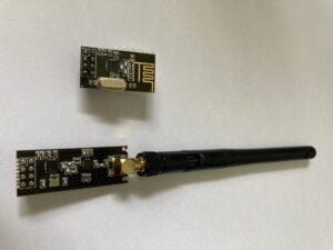
Antenna Types
The modules can have either an onboard antenna or an external antenna for transmitting and receiving radio signals. The onboard antenna can transmit up to around 100m, whilst an external antenna can reach over 1km in optimal conditions.
Power Requirements
The NRF24L01 module operates at a supply voltage of 3.3 volts and consumes minimal power during operation, making it suitable for battery-powered applications. Ensure that your power supply can deliver sufficient current to meet the module’s requirements.
Interface
The NRF24L01 module communicates with the microcontroller using the Serial Peripheral Interface (SPI) protocol. This allows for high-speed data exchange and configuration between the module and the microcontroller.
NRF24L01 Communication Protocols
Here’s an overview of the communication protocol for the NRF24L01:
Frequency:
The NRF24L01 operates in the 2.4GHz ISM (Industrial, Scientific, and Medical) band, which is a license-free frequency band available globally.
Channels:
It can operate on 126 different channels with a 1MHz spacing, allowing multiple modules to coexist without interference.
Modulation:
The NRF24L01 uses GFSK (Gaussian Frequency Shift Keying) modulation for data transmission, which effectively balances between spectrum efficiency and resilience to noise.
Data Rates:
It supports configurable data rates from 250kbps to 2Mbps, allowing flexibility in various applications. Lower data rates are often preferred for longer range and better reliability.
Addressing:
The module supports both point-to-point and multi-node communication. Each device in the network is assigned a unique address, typically consisting of a pipe address (up to 5 bytes) and an optional payload address (up to 5 bytes). This allows for flexible addressing schemes suitable for different network topologies.
Packet Structure:
Communication with the NRF24L01 occurs through packets. Each packet typically includes a preamble, a sync word, an address field, a payload field (containing user data), and optional CRC (Cyclic Redundancy Check) for error detection.
Enhanced ShockBurst (ESB) Mode:
This is a built-in protocol in the module that provides features such as automatic packet handling, ACK (Acknowledgment) mechanism, retransmissions, and packet buffering. ESB simplifies the implementation of reliable communication protocols on top of the NRF24L01.
SPI Interface:
The NRF24L01 is controlled via an SPI (Serial Peripheral Interface) bus, allowing easy integration with microcontrollers. Commands are sent to the module via SPI, and status and data are read back from it.
To use the NRF24L01 module in your project, you typically interface it with a microcontroller (like Arduino, Raspberry Pi, etc.) using SPI communication and control it using libraries provided by Nordic Semiconductor or third-party libraries developed by the community. These libraries abstract the low-level details of the NRF24L01 communication protocol, allowing you to focus on application development.
Serial Communication Interface (SPI)
The NRF24L01 module utilizes the Serial Peripheral Interface (SPI) protocol for communication with the microcontroller. Understanding how data is transmitted and received between the module and the microcontroller is essential for effectively using the NRF24L01 module in your projects.
SPI Protocol
SPI is a synchronous serial communication protocol commonly used to exchange data between microcontrollers and peripheral devices. It consists of four main signals:
SCK (Serial Clock): This signal provides the clock for synchronous communication between the microcontroller and the NRF24L01 module. Data is transferred on each rising or falling edge of the clock signal.
MOSI (Master Out Slave In): This signal carries data from the microcontroller (master) to the NRF24L01 module (slave) during data transmission.
MISO (Master In Slave Out): This signal carries data from the NRF24L01 module (slave) to the microcontroller (master) during data reception.
CSN (Chip Select Not): This signal is used to select the NRF24L01 module for communication. When the CSN pin is set low, the module is enabled for data transfer.
Data Transmission
The NRF24L01 module supports both single-byte and multi-byte data transmission modes. Data is typically transmitted in packets, which can include payload data, addressing information, and control bits.
Addressing: Each NRF24L01 module is assigned a unique address that identifies it within a network. This address is used to ensure that data is transmitted to the intended recipient.
Acknowledgment: The NRF24L01 module supports automatic acknowledgment of received packets, allowing for reliable data transmission. After receiving a packet, the receiving module sends an acknowledgment signal back to the transmitting module to confirm successful reception.
Configuration
Before using the NRF24L01 module for communication, it must be configured with appropriate settings such as data rate, channel frequency, and addressing mode. These settings can be adjusted via SPI commands sent from the microcontroller to the module.
Protocol Stack
The NRF24L01 module implements a simple protocol stack consisting of physical layer (PHY) and link layer (LL) functionalities. The PHY layer handles the transmission and reception of radio signals, while the LL layer manages packetization, addressing, and error detection.
Understanding the communication protocol of the NRF24L01 module is essential for writing code to interact with it and implementing reliable wireless communication in your projects.
Installing Arduino IDE Libraries
To utilize the NRF24L01 module with Arduino, it’s important to install the appropriate libraries that provide support for interfacing with the module.
Follow these steps to install the required libraries:
Open the Arduino IDE:
Launch the Arduino Integrated Development Environment (IDE) on your computer.
Navigate to the Library Manager:
Go to the “Sketch” menu, hover over “Include Library,” and select “Manage Libraries…” This will open the Library Manager window.
Search for NRF24L01 Libraries:
In the Library Manager, type “NRF24L01” in the search bar. This will filter the libraries to display only those related to the NRF24L01 module.
Install the Library:
Locate the library named “RF24 by TMRh20” (or similar) and click on it. Then, click the “Install” button to download and install the library.
Verify Installation:
Once the library is installed, you should see a green “INSTALLED” label next to the library name in the Library Manager.
Install SPI Library (if needed):
If the SPI library is not already installed, you can install it by searching for “SPI” in the Library Manager and following the same steps to install it.
Close the Library Manager:
After installing the necessary libraries, close the Library Manager window to return to the Arduino IDE.
Verify Library Installation:
To ensure that the libraries are installed correctly, you can open one of the example sketches provided with the library. Go to the “File” menu, hover over “Examples,” navigate to the installed NRF24L01 library, and select one of the example sketches. If the sketch opens without errors, the library has been successfully installed.
Begin Using the Library:
With the libraries installed, you’re now ready to start writing your Arduino sketches to communicate with the NRF24L01 module. Include the necessary library headers at the beginning of your sketches, such as #include <RF24.h>, to access the library functionalities.
By following these steps, you can easily install the required libraries for working with the NRF24L01 module in Arduino projects and unlock its full potential for wireless communication.
Conclusion
The NRF24L01 radio module offers a powerful solution for wireless communication in a wide range of projects. With their compact size, low power consumption, and robust communication protocols, they are ideal for applications ranging from IoT devices and sensor networks to remote control systems and beyond.
If you’re ready for creating your first project with the NRF24L01 module, check out our guide for Building Your First Radio
“Disclosure: This post contained Amazon weblinks. We are a participant in the Amazon Services LLC Associates Program, an affiliate advertising program designed to provide a means for us to earn fees by linking to Amazon.co.uk and affiliated sites. This means that when you click on product links and make a purchase on Amazon, we may receive a small commission at no extra cost to you. We only recommend products that we genuinely believe in, and think will be of value to our readers. Your support through these links helps us continue to provide quality content to you. Thank you for your support!“
