
Resistance is Futile
Ever found yourself rummaging through a pile of resistors, only to be stumped by their cryptic color codes? Well, worry no more! Introducing the ultimate DIY resistor tester powered by Arduino. This ingenious device is your ticket to quickly and effortlessly identifying resistors and understanding their values. Gone are the days of guesswork and frustration. Simply insert your mysterious resistor and watch as this smart gadget reveals its resistance and value, providing you with the knowledge you need in an instant.
Say goodbye to the hassle of deciphering color bands and hello to a more efficient, precise, and enjoyable electronics experience. Join us on this exciting journey into the world of resistor testing and unlock the potential of your electronic projects like never before.
LearnElectronics YouTube Channel
I follow a channel on YouTube LearnElectronics. It’s a decent no thrills learning platform for Electronics. Paul the channels creator has over 130k subscribers.
LearnElectronics covers everything from electronics basics to programming microcontrollers to even tearing down devices to show us what’s inside. It’s a good show, check it out!
In one video Paul created a resistance tester for identifying random resistors fast. It didn’t work, but this is why I like this channel, creation on the fly with all its faults. Paul asked if anyone out there could help. I jumped at the chance to help out on the channel plus I had a pretty good idea why it didn’t work. Once I finished the project, I sent the code to Paul.
Paul was impressed with the results, and you can see my tester being featured on his channel below:
How to Build My Resistor Tester
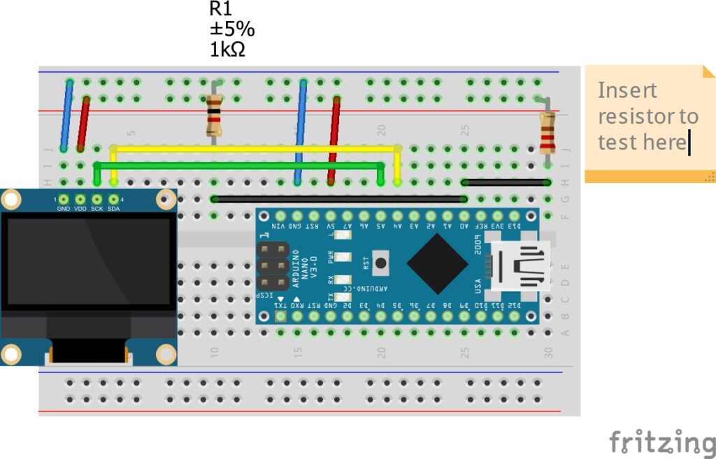
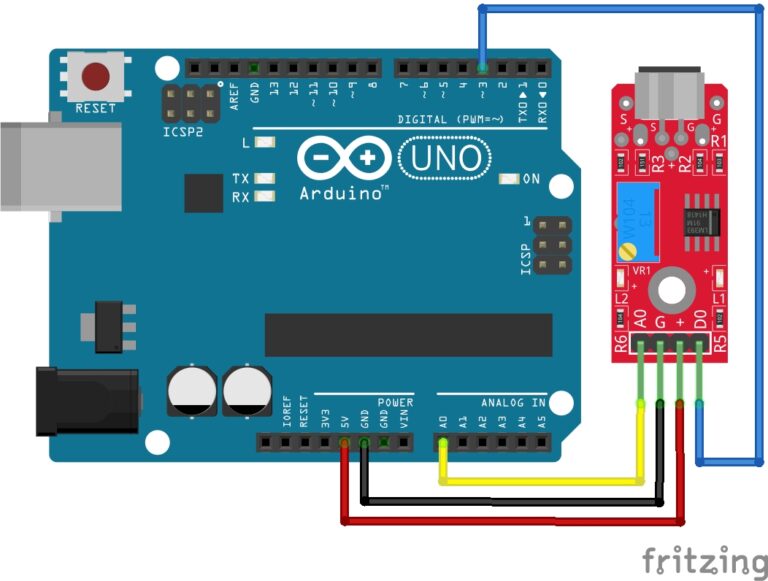
The Circuit:
I’ll break this down for you. The Connections are as follows:
Mini-OLED:
- GNG to GND on the Arduino.
- VCC to 5V on the Arduino.
- SCK to A5 on the Arduino.
- SDA to A4 on the Arduino.
1K Resistor:
This resistor is permanent.
- Connect one leg to A0 on the Arduino.
- Connect other leg to GND on the Arduino.
Random Resistor to Test:
- Connect one leg to A0 on the Arduino.
- Connect the other leg to 5V on the Arduino.
Follow the diagram below:
The Code:
#include <Wire.h> //library for I2C
#include <Adafruit_SSD1306.h>//OLED driver
#include <Adafruit_GFX.h>

#define SCREEN_WIDTH 128   // OLED display width, in pixels
#define SCREEN_HEIGHT 64  // OLED display height, in pixels
#define OLED_RESET 4     //required by the OLED driver

Adafruit_SSD1306 display(128, 64, &Wire, OLED_RESET); //initiate library

int analogPin = 0;      //pin to read voltage divider
int raw = 0;           //reading from pin
int Vin = 5;          //voltage out from arduino
float Vout = 0;      //initial value
float R1 = 1000;    //"Known" resistor connects between Gnd & Analog Reading point(between resistors)
float R2 = 0;      //"Unknown" resistor connects between 5v & Analog Reading point(between resistors)
float buffer = 0; //initial buffer value
int tm=2000;     //the time it displays final result (which resistor you have entered)

void setup()   {
  display.begin(SSD1306_SWITCHCAPVCC, 0x3C); //startup the display
  display.display();
  delay(500);
  display.setTextColor(WHITE);
  display.setTextSize(3);
  display.setCursor(20,16);
  display.clearDisplay();
  display.print("Basic");
  display.display();
  delay(1000);
  display.clearDisplay();
  display.setTextSize(5);
  display.setCursor(20,16);
  display.println("Ohm");
  display.display();
  delay(1000);
  display.clearDisplay();
  display.setTextSize(3);
  display.setCursor(20,16);
  display.print("Meter");
  display.display();
  delay(1000);
  display.clearDisplay();
}

void loop() {
  display.clearDisplay();
  display.setCursor(0,0);
  display.setTextSize(2);
  display.setTextColor(WHITE);
  delay(100);
  raw = analogRead(analogPin);    //read voltage at analog pin 0

  if (raw) {                     //if there is a reading, then lets begin
    buffer = raw * Vin;         //multiply the reading by the value of vin
    Vout = (buffer) / 1024.0;  //set value of Vout to the whats in the buffer divided by 1024, the max value of the ADC
    buffer = (Vin / Vout) - 1;//now make the buffer voltage in divided by voltage out -1
    R2 = R1 * buffer;        //the value of the unknown is the known multiplied by the buffer
    display.clearDisplay();
    display.println("Volts");
    display.println("=");
    display.print(Vout);
    display.print("v");
    display.display();
    delay(1500);
    display.clearDisplay();
    delay(100);
    display.setCursor(0,0);
    display.println("Resistance");
    display.println("=");
    display.print(R2);
    display.display();
    delay(1500); //wait 3 seconds so it can be read
  }
  display.clearDisplay();
  display.setCursor(25,20);
  display.setTextSize(2);
  display.setTextColor(WHITE);

  if (R2 > 4.0 && R2 < 16.0) {
    display.print("10 Ohms");   //Ω
    display.display();
    delay(tm);
  }

  if (R2 > 75.0 && R2 < 125.0) {
    display.print("100 Ohms");
    display.display();
    delay(5000);
  }

  if (R2 > 200.0 && R2 < 240.0) {
    display.print("220 Ohms");
    display.display();
    delay(tm);
  }

  if (R2 > 300.0 && R2 < 350.0) {
    display.print("330 Ohms");
    display.display();
    delay(tm);
  }

  if (R2 > 900.0 && R2 < 1100.0) {
    display.print("1k Ohms");
    display.display();
    delay(tm);
  }

  if (R2 > 1800.0 && R2 < 2200.0) {
    display.print("2k Ohms");
    display.display();
    delay(tm);
  }

  if (R2 > 4800.0 && R2 < 5200.0) {
    display.print("5k Ohms");
    display.display();
    delay(tm);
  }

  if (R2 > 9000.0 && R2 < 11000.0) {
    display.print("10k Ohms");
    display.display();
    delay(tm);
  }

  if (R2 > 12500.0) {
    display.setCursor(0,0);
    display.println("   Out");
    display.println("   Of");
    display.print("   Range");
    display.display();
    delay(2000);
  }
}
Upload the Code:
With your circuit built, go ahead and upload the code to your Arduino. Until you add a resistor to test you will see the “Out of Range” message displayed. You will also see the “Out of Range” message displayed if your resistor was not accounted for in the code.
Which Resistors are Accounted for?
Here is a list of all resistors accounted for in the code:
- 10k Ohms
- 5k Ohms
- 2k Ohms
- 1k Ohms
- 330 Ohms
- 220 Ohms
- 100 Ohms
- 10 Ohms
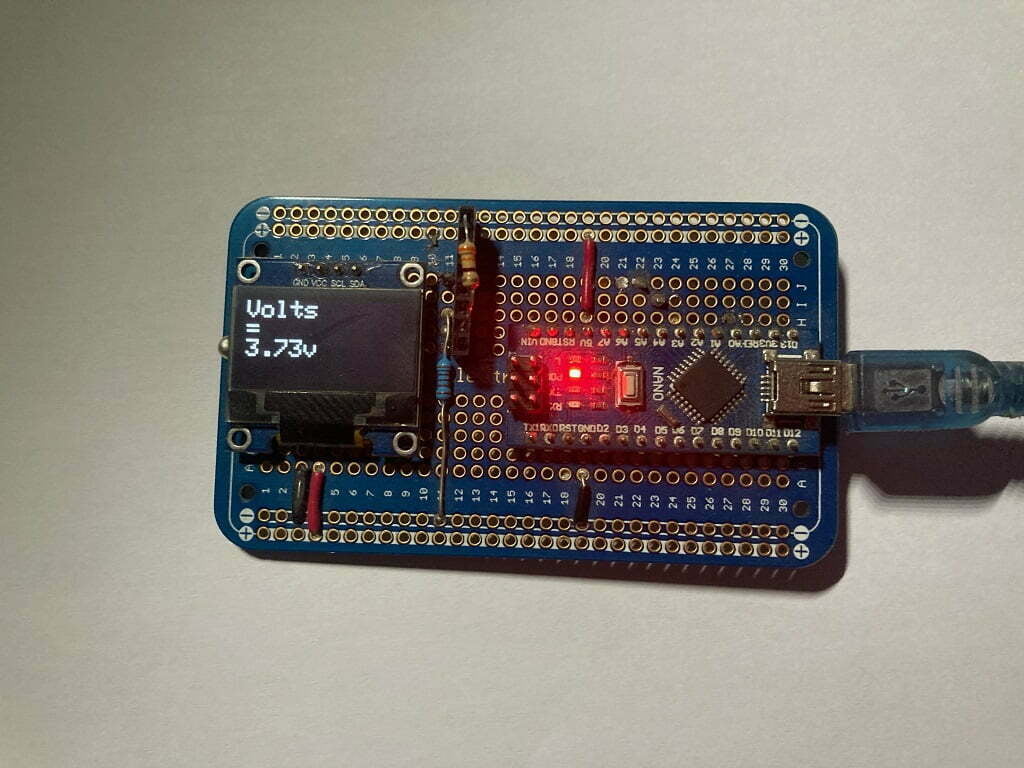
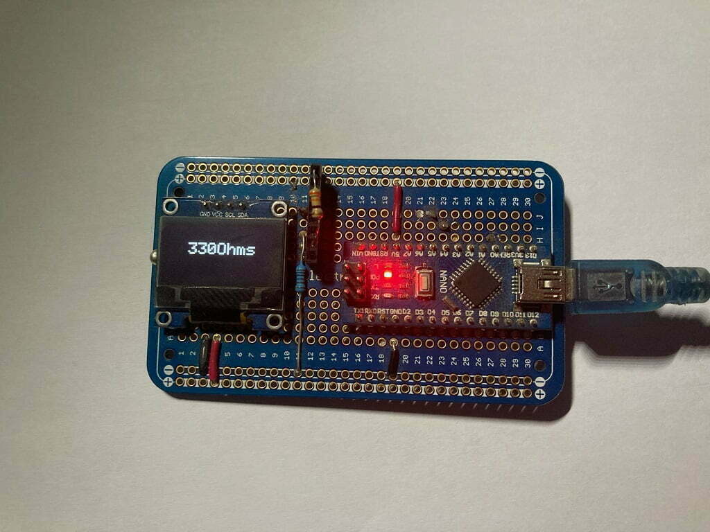
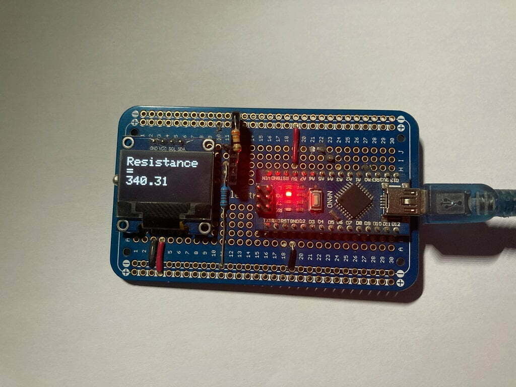
Images of my Final Project
Below are some images of my final project. I use the very often. Finding resistors on the floor happens a lot so having this available makes identifying them much easier and faster.
Conclusion
Embrace the power of technology and take the guesswork out of your electronic projects with this DIY resistor tester. With its simplicity and efficiency, you’ll wonder how you ever managed without it. So, why wait? Get ready to conquer your resistor-related challenges and elevate your electronics game. Build your Arduino powered resistor tester today and embark on a journey of precision, productivity, and innovation.
Happy Testing and Happy Tinkering!
Recommendations:
The Elegoo Super Starter Kit
If you don’t already own any Arduino hardware, we highly recommend this kit as it has everything you need to start programming with Arduino. You can find out more about this kit, including a list of its components here: Elegoo Super Starter Kit
You can find this kit on Amazon here: Elegoo Super Starter Kit
The 0.96-inch Mini-OLED Display
We highly recommend this mini-OLED bundle of five 0.96-inch OLED displays. We have bought these before and they all worked perfectly. You can read more about the mini-OLED here: Mini-OLED
You can find this bundle on Amazon here: OLED Displays
Elegoo Nano (Arduino Compatible)
We have bought these Nano boards many times and can highly recommend them. There are three Nano boards in this pack making them a total bargain for everyone.
You can find this pack on Amazon here: Arduino Nano
ESP8266 D1-Mini
D1-Mini is an Arduino compatible Wi-Fi board based on an ESP-8266-12F. This WLAN board has 9 digital I/O pins.
You can find this board on Amazon here: D1-Mini
