

Welcome to the World of Sensors and Modules with Arduino!
The Shock Sensor Module, also known as a Vibration Switch Module, can detect vibrations or sudden impacts. It typically consists of a small module that includes a spring-based mechanism or a metal ball that moves and triggers the sensor when subjected to vibration or shock. In this sensors and modules guide, we’ll explore its working principle, key features, applications, and how it can enhance your Arduino projects.
If you’re new to Arduino, why not take a look at our Getting Started with Arduino guides. These guides are designed for beginners to learn the fundamental basics of Arduino programming.
How the Shock Sensor Works
When a shock or vibration occurs, the sensor detects it and generates an electrical signal, which can be read by a microcontroller or other electronic device connected to the sensor. This can be useful in various applications such as detecting knocks on doors, monitoring movement or impacts, or as part of an alarm system to sense unauthorized access. It’s a handy component for projects involving motion detection or where you need to detect physical disturbances.
Features and Specifications:
- Operating Voltage: 5V
- Size: 19 x 15.5mm
- Output Signal: Digital
- Compatibility: This sensor is also compatible with other devices like the Raspberry Pi, ESP32, and ESP8266 etc…
Necessary Equipment:
- Arduino board (e.g., Arduino Uno)
- Shock Sensor Module
- Jumper wires
- Breadboard (optional)
Pin Configuration
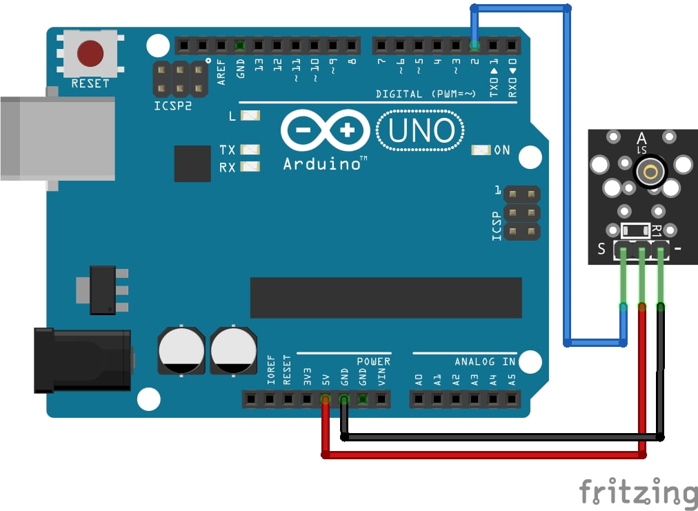
Wiring the Shock Sensor Module to an Arduino is fairly simple. The connections are as follows:
- S on the Shock Sensor Module to Digital pin 2 on the Arduino.
- VCC (Middle Pin) on the Shock Sensor Module to 5V Arduino.
- – on the Shock Sensor Module to GND on the Arduino.
Pin labels may vary.
KY-002 Vibration Switch Module Fritzing Part is created by arduinomodules.info and published under Creative Commons Attribution-ShareAlike 4.0 International license
Basic Arduino Code Example
const int shockSensorPin = 2; // Connect the sensor to digital pin 2

void setup() {
  Serial.begin(9600); // Start serial communication
  pinMode(shockSensorPin, INPUT); // Set the sensor pin as input
}

void loop() {
  int sensorValue = digitalRead(shockSensorPin); // Read the sensor value

  if (sensorValue == LOW) { // If sensor detects a shock/vibration
    Serial.println("Shock detected!"); // Print message to Serial Monitor
    delay(1000); // Delay to avoid multiple rapid detections
  }
}
Breaking Down the Code
Pin Declarations
const int shockSensorPin = 2;: Defines a constant integer variableshockSensorPinand assigns it to digital pin 2, where the sensor is connected.
Setup Function
Serial.begin(9600);: Initializes serial communication at a baud rate of 9600.pinMode(shockSensorPin, INPUT);: Sets theshockSensorPinas an input pin, indicating that it will be reading the sensor’s output.
Loop Function
int sensorValue = digitalRead(shockSensorPin);: Reads the value from theshockSensorPinand stores it in thesensorValuevariable as either HIGH or LOW.if (sensorValue == LOW) {: Checks if thesensorValueis LOW, indicating a shock or vibration detection.Serial.println("Shock detected!");: If the sensor reads LOW, it prints “Shock detected!” to the Serial Monitor.delay(1000);: Introduces a delay of 1 second to prevent multiple rapid detections, allowing time between each detection.
This code continuously loops, reading the sensor’s output value. When the sensor output goes LOW (which indicates a shock or vibration based on your sensor’s behavior), it triggers the “Shock detected!” message to be printed in the Serial Monitor.
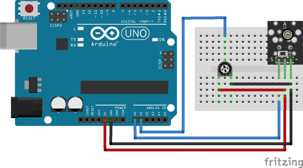
Integrating Sensitivity Control
The example above is very basic and just takes HIGH or LOW digital readings, giving us no control over the sensor. By adding a Potentiometer and taking analog readings, we can adjust how sensitive the shock sensor is allowing us to cut down on any environmental noise interference.
Necessary Equipment:
- Arduino board (e.g., Arduino Uno)
- Shock Sensor Module
- 10K ohm Potentiometer
- Breadboard
- Jumper wires
Arduino Code Example
const int shockSensorPin = A0; // Connect the sensor to analog pin A0
const int potentiometerPin = A1; // Connect potentiometer to analog pin A1
int threshold = 100; // Initial threshold value

void setup() {
  Serial.begin(9600); // Start serial communication
  pinMode(shockSensorPin, INPUT); // Set the sensor pin as input
  pinMode(potentiometerPin, INPUT); // Set potentiometer pin as input
}

void loop() {
  int sensorValue = analogRead(shockSensorPin); // Read the sensor value
  int potValue = analogRead(potentiometerPin); // Read potentiometer value

  threshold = map(potValue, 0, 1023, 0, 1023); // Map potentiometer value to threshold range

  if (sensorValue < threshold) { // If sensor value falls below the threshold
    Serial.print("Shock detected! Sensor value: "); // Print message to Serial Monitor
    Serial.println(sensorValue);
    delay(1000); // Delay to avoid multiple rapid detections
  }
}
Breaking Down the Code
Pin and Variable Declarations
const int shockSensorPin = A0;: Defines the analog pin to which the shock sensor is connected.const int potentiometerPin = A1;: Specifies the analog pin where the potentiometer is connected.int threshold = 100;: Initializes the threshold value for shock detection.
Setup Function
Serial.begin(9600);: Starts serial communication at a baud rate of 9600.pinMode(shockSensorPin, INPUT);: Sets the shock sensor pin as input for reading analog values.pinMode(potentiometerPin, INPUT);: Sets the potentiometer pin as input for reading analog values.
Loop Function
int sensorValue = analogRead(shockSensorPin);: Reads the analog value from the shock sensor.int potValue = analogRead(potentiometerPin);: Reads the analog value from the potentiometer.threshold = map(potValue, 0, 1023, 0, 1023);: Maps the analog readings from the potentiometer (ranging from 0 to 1023) to adjust the sensitivity threshold for shock detection.if (sensorValue < threshold) { /* ... */ }: Checks if the sensor value falls below the adjusted threshold.Serial.print("Shock detected! Sensor value: ");: Displays a message in the Serial Monitor when a shock is detected, along with the sensor value.delay(1000);: Introduces a delay to prevent multiple rapid detections and ensure smoother serial output.
Potentiometer Usage
- The potentiometer’s knob can be turned to vary the sensitivity threshold, allowing users to adjust the sensor’s sensitivity by changing the threshold value dynamically.
By using the potentiometer readings to dynamically modify the threshold value, users can fine-tune the sensitivity of the shock sensor according to their preferences or project requirements. Adjusting the potentiometer will alter the threshold for detecting shocks or vibrations.
Troubleshooting Issues
Wiring: Double-check the wiring between the sensor and the Arduino. Ensure that the connections are correct and stable. Sometimes incorrect connections or loose wires can lead to constant maximum readings.
Sensor Compatibility: Confirm that the sensor is compatible with the voltage levels of the Arduino’s analog input pins. Some sensors might operate at different voltage levels that might exceed the Arduino’s maximum input voltage, leading to constant maximum readings.
Sensor Limitation: Some sensors might have a fixed output range that could saturate at the maximum value regardless of the actual stimulus. Review the sensor’s datasheet or documentation to understand its output range and characteristics.
Environmental Interference: Environmental factors or noise could potentially influence the sensor readings. Try testing the sensor in a different environment or isolate it from sources of interference.
Code or Circuit Issue: Review the code and circuit design to ensure there are no issues affecting the sensor readings. Check for any conflicting code or incorrect configurations that might lead to constant maximum readings.
If you’ve verified the wiring, compatibility, and ruled out external factors, it’s possible that the sensor itself might have limitations or there could be an underlying issue with the setup that’s causing this consistent maximum reading. Double-check the sensor specifications and consider testing the sensor in a different setup or with a different Arduino board to isolate the issue further.
Applications and Usage Scenarios
Security Systems
Detect unauthorized entry by attaching these modules to doors or windows. When a shock or force is detected, it triggers an alarm.
Vehicle Security
Integrate shock sensors into car alarm systems to detect attempted break-ins or collisions.
Airbag Deployment
In cars, shock sensors can assist in triggering airbag deployment during collisions.
Machinery Monitoring
Detect abnormal vibrations or shocks in machinery to indicate potential malfunctions or maintenance needs.
Structural Health Monitoring
Install these modules in buildings or bridges to monitor structural integrity and detect stress or damage.
Gaming Controllers
Use shock sensors to enhance gaming experiences by detecting gestures or impacts in gameplay.
Activity Trackers
Implement shock sensors in fitness trackers to detect movement patterns, falls, or impacts during physical activities.
Sports Equipment
Enhance sports gear with these modules to measure impact forces or detect improper usage.
Collision Avoidance
Equip robots or drones with shock sensors for collision detection and avoidance during navigation.
Earthquake Detection
Utilize sensitive shock sensors to detect seismic activity and monitor earthquakes.
These applications highlight the versatility of shock sensors in various industries, from enhancing security to enabling safety features in vehicles and even monitoring structural integrity in construction. Their ability to detect sudden impacts or vibrations makes them invaluable in numerous real-world scenarios.
Conclusion
In this sensors and modules guide, we explained the functionality of the Shock Sensor Module, exploring its working principles, and demonstrating how to interface it with an Arduino for practical applications. Mastering the integration of shock sensors with Arduino involves a blend of technical understanding, troubleshooting prowess, and continuous experimentation.
Discover the endless possibilities for Arduino projects with more of our Sensors and Modules guides.

