
Welcome to the World of Sensors and Modules with Arduino!
In this guide we will be building a basic transmitter and receiver using the NRF24L01 with Arduino. The NRF24L01 is a versatile and cost-effective radio frequency (RF) transceiver module that enables wireless communication between microcontroller-based devices. Developed by Nordic Semiconductor, the NRF24L01 module operates in the 2.4 GHz ISM (Industrial, Scientific, and Medical) band, providing a convenient and widely available frequency range for wireless communication. Please read our Introduction to the NRF24L01 to help you get to know the module better before continuing on with this guide to creating your first radio with Arduino.
If you’re new to Arduino, why not take a look at our Getting Started with Arduino guides. These guides are designed for beginners to learn the fundamental basics of Arduino programming.
Installing Required IDE Libraries for the NRF24L01
To utilize the NRF24L01 module with Arduino, you’ll need to install the appropriate libraries that provide support for interfacing with the module.
Follow these steps to install the necessary libraries:
Open the Arduino IDE:
Launch the Arduino Integrated Development Environment (IDE) on your computer.
Navigate to the Library Manager:
Go to the “Sketch” menu, hover over “Include Library,” and select “Manage Libraries…” This will open the Library Manager window.
Search for NRF24L01 Libraries:
In the Library Manager, type “NRF24L01” in the search bar. This will filter the libraries to display only those related to the NRF24L01 module.
Install the Library:
Locate the library named “RF24 by TMRh20” (or similar) and click on it. Then, click the “Install” button to download and install the library.
Verify Installation:
Once the library is installed, you should see a green “INSTALLED” label next to the library name in the Library Manager.
Additional Libraries (Optional):
Depending on your specific project requirements, you may need to install additional libraries for related functionalities, such as RF24 (a driver for NRF24L01 modules) or SPI (for SPI communication). Search for these libraries in the Library Manager and install them if needed.
Close the Library Manager:
After installing the necessary libraries, close the Library Manager window to return to the Arduino IDE.
Verify Library Installation:
To ensure that the libraries are installed correctly, you can open one of the example sketches provided with the library. Go to the “File” menu, hover over “Examples,” navigate to the installed NRF24L01 library, and select one of the example sketches. If the sketch opens without errors, the library has been successfully installed.
Begin Using the Library:
With the libraries installed, you’re now ready to start writing your Arduino sketches to communicate with the NRF24L01 module. Include the necessary library headers at the beginning of your sketches, such as #include <RF24.h>, to access the library functionalities.
By following these steps, you can easily install the required libraries for working with the NRF24L01 module in Arduino projects and unlock its full potential for wireless communication.
Necessary Equipment
With the correct libraries installed we are now ready to begin building our radios. Here is a list of all required equipment you need to complete this project:
- x2 NRF24L01 modules
- x2 Arduino Nano boards (e.g., Arduino Uno, Nano, etc… we will be working with the Nano for this, but you can use whatever you have at hand)
- Jumper wires
- Breadboards (optional)
Pin Configuration
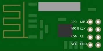
The module typically has eight pins: VCC, GND, CE, CSN, SCK, MOSI, MISO, and IRQ. Look closely at the image above, this is the orientation of the pins for the NRF24L01 module.
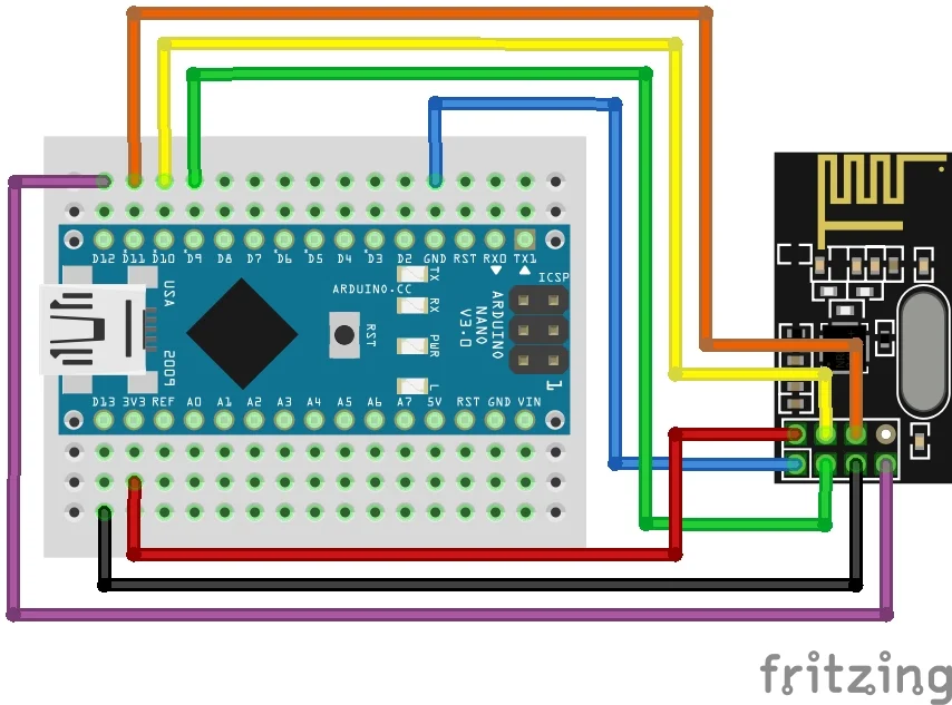
Follow these connections as carefully as possible, any incorrect wiring will result in a failure to communicate between the two NRF24L01 modules or may even cause irreversible damage to them:
- VCC on the NRF24L01 module to 3.3V on the Arduino (unless you are using the base board then you can connect it to 5V).
- GND on the NRF24L01 module to GND on the Arduino.
- CSN (Chip Select) on the NRF24L01 module to Digital pin 10 on the Arduino.
- CE (Chip Enabled) on the NRF24L01 module to Digital pin 9 on the Arduino.
- SCK (Serial Clock) on the NRF24L01 module to Digital pin 13 on the Arduino.
- MOSI (Master Out Slave in) on the NRF24L01 module to Digital pin 11 on the Arduino.
- MISO (Master in Slave Out) on the NRF24L01 module to Digital pin 12 on the Arduino.
- IRQ: This pin is optional and may be left unconnected as we won’t be using it for this guide. It is used for interrupt handling.
Build two of these, one for the transmitter and one for the receiver. Double-check all connections to ensure that there are no loose connections or incorrect wiring.
Creating the Transmitter
Now that we’ve set up the NRF24L01 module and installed the necessary libraries, let’s look at the code for creating a simple transmitter with the NRF24L01 module.
#include <SPI.h>
#include <RF24.h>
#define CE_PIN 9 #define CSN_PIN 10 RF24 radio(CE_PIN, CSN_PIN);
void setup() { Serial.begin(9600); radio.begin(); radio.setPALevel(RF24_PA_LOW); // Set power level to low radio.openWritingPipe(0xF0F0F0F0E1LL); // Set the transmitting address }
void loop() { const char* message = "Hello, NRF24L01!"; radio.write(message, strlen(message)); Serial.println("Message sent!"); delay(1000); // Delay between transmissions }
This is a very basic example for creating the transmitter. I have kept this code very simple to make it as easy to follow as possible.
Breaking Down the Code
Let’s take a closer look at what the code is doing:
Include the Required Libraries
At the beginning of the Arduino sketch, we include the necessary library headers for the NRF24L01 module. Think of libraries as collections of pre-written code that we can use to make our program do specific tasks without needing to write everything from scratch.
#include <SPI.h> #include <RF24.h>
Define NRF24L01 Module Pins
We then define the pins used to communicate with the NRF24L01 module. These are the CE (Chip Enabled) and CSN (Chip Select) pins, which we connect to digital pins 9 and 10 on the Arduino:
#define CE_PIN 9 #define CSN_PIN 10
Initialize the RF24 Object
Next, we create an instance of the RF24 class and initialize it with the CE and CSN pins.
RF24 radio(CE_PIN, CSN_PIN);
Setup Function
In the setup function, we initialize the serial monitor for debugging purposes and displaying communication messages:
Serial.begin(9600);
We then start the radio with:
radio.begin();
Then we set the Power Amp level to low:
radio.setPALevel(RF24_PA_LOW); // Set power level to low
Lastly, we set the transmitting address:
radio.openWritingPipe(0xF0F0F0F0E1LL); // Set the transmitting address
This is the address parameter passed to the openWritingPipe() method. It’s a hexadecimal value that represents the transmitting address. Using a hexadecimal address for the NRF24L01 module’s transmitting address provides a clear, concise, and standardized way to specify the destination address for data transmission. It aligns well with protocol conventions, facilitates human readability, and ensures compatibility with other devices and libraries.
Loop Function
In the loop function, we write code to repeatedly send data using the NRF24L01 module. In this basic example, we send a simple message. First, we create the simple message contained inside the variable called message:
const char* message = "Hello, NRF24L01!";
Then we transmit the message using:
radio.write(message, strlen(message));
Lastly, we print to the console that the message has been sent and then add a short delay of one second before transmitting it again:
Serial.println("Message sent!");
delay(1000); // Delay between transmissions
That’s the basic code for creating a simple transmitter, next we will work on the receiver.
About the Power Amp Level
In the code above we have the command:
radio.setPALevel(RF24_PA_LOW);
Here are all the commands for each of the available power levels:
- RF24_PA_MIN: This sets the minimum power level, usually the lowest available power level. It’s similar to RF24_PA_LOW but may have slightly different characteristics depending on the module.
- RF24_PA_LOW: This sets the power level to low, offering reduced transmission power for lower energy consumption.
- RF24_PA_HIGH: This sets the power level to high, providing increased transmission power for longer range communication. It consumes more energy compared to lower power levels.
- RF24_PA_MAX: This sets the maximum power level, typically the highest available power level. It offers the maximum transmission power for extended range but consumes the most energy.
- RF24_PA_ERROR: This is an error code indicating an invalid power amplifier level. It’s returned by the library if an invalid power level is specified.
When selecting a power level for your NRF24L01 module, consider the following factors:
- Transmission Range: Higher power levels generally result in longer transmission ranges, making them suitable for applications requiring communication over greater distances.
- Power Consumption: Higher power levels consume more energy, which may be a concern in battery-powered applications or situations where power efficiency is critical.
- Interference: Higher power levels can increase the likelihood of interference with other wireless devices operating in the same frequency band. It’s important to balance range requirements with potential interference issues.
- Regulatory Compliance: Different regions have regulations governing the maximum allowed transmission power for wireless devices. Ensure that your selected power level complies with local regulations to avoid legal issues.
To set a different power level, you can simply replace RF24_PA_LOW with one of the other available options in the setPALevel() method.
Creating the Receiver
Now that we have the transmitter ready, we need to create a basic receiver to capture the transmitted data.
#include <SPI.h>
#include <RF24.h>
#define CE_PIN 9
#define CSN_PIN 10
RF24 radio(CE_PIN, CSN_PIN);
void setup() {
Serial.begin(9600);
// Initialize the NRF24 module
if (!radio.begin()) {
Serial.println("Failed to initialize NRF24 module. Please check wiring.");
while (1); // Loop indefinitely if initialization fails
}
// Set the receiving address
radio.openReadingPipe(1, 0xF0F0F0F0E1LL);
// Start listening for incoming messages
radio.startListening();
}
void loop() {
// Check if there's a message available
if (radio.available()) {
char message[32] = {0};
// Read the message from the NRF24 module
radio.read(message, sizeof(message));
// Print the received message to the serial monitor
Serial.print("Received message: ");
Serial.println(message);
}
}
This is also a basic example for creating the receiver. I have kept this code simple to make it as easy to follow as possible.
Breaking Down the Code
Let’s take a closer look at what this code is doing:
Include Libraries
At the beginning of the Arduino sketch, we include the necessary library headers for the NRF24L01 module.
#include <SPI.h> #include <RF24.h>
Define NRF24L01 Module Pins
We then define the pins used to communicate with the NRF24L01 module. These are the CE (Chip Enabled) and CSN (Chip Select) pins, which we connect to digital pins 9 and 10 on the Arduino:
#define CE_PIN 9 #define CSN_PIN 10
Initialize the RF24 Object
Next, we create an instance of the RF24 class and initialize it with the CE and CSN pins.
RF24 radio(CE_PIN, CSN_PIN);
Setup Function
In the setup function, we initialize the serial monitor for debugging purposes and displaying communication messages:
Serial.begin(9600);
Next, we start the radio, but this time I have added a conditional statement that will check if the radio initializes correctly. If the radio fails to start, the code will be stuck in a loop indefinitely and an error report is sent to the console:
if (!radio.begin()) {
Serial.println("Failed to initialize NRF24 module. Please check wiring.");
while (1);
}Then we set the receiver’s address:
radio.openReadingPipe(1, 0xF0F0F0F0E1LL);
Lastly, we set the radio to start listening for transmissions:
radio.startListening();
Loop Function
In the loop function, we write code to handle the transmitted data using the NRF24L01 module. Firstly, we use a conditional statement to check if there is a transmission available:
if (radio.available()) {
}Within the conditional statement, we create a space in memory to hold the transmitted message:
char message[32] = {0};char message[32] = {0}; means: “Create a space in memory called message that can hold up to 32 characters and fill it with zeros to start.” This prepares the message array to receive a new message without any leftover data from previous operations.
Next, we read the transmitted message using:
radio.read(message, sizeof(message));
Lastly, we print the received message to the console with:
Serial.print("Received message: ");
Serial.println(message);That’s a complete breakdown of each part of the code explained in simpler terms for beginners. Each segment does a specific job to help us communicate with the NRF24L01 module and handle incoming messages.
Test the Sketches
Upload the sketches to your Arduino boards and open the serial monitor for the receiver in the Arduino IDE. You should see the transmitted message.
If you encounter any issues, refer to the troubleshooting section in the next part of this guide or consult the documentation for the NRF24L01 module and the RF24 library.
Troubleshooting the NRF24L01
Encountering issues during the setup and operation of the NRF24L01 module is not uncommon, but with proper troubleshooting techniques, you can quickly identify and resolve problems. When I began writing this guide, I had problems at first, even with these very basic code examples which I was sure should work. After a couple hours of debugging, I decided to order some new NRF24L01 modules. They arrived the next day and then the code worked just as expected.
Here are some common issues and troubleshooting steps to help you get back on track:
Connectivity Issues:
Check Wiring: Ensure that all connections between the NRF24L01 module and the Arduino are correct and secure. Double-check the pin connections and verify that the module is receiving power.
Antenna Placement: Position the module’s antenna properly to maximize signal strength and minimize interference. Avoid placing the antenna near metal objects or other electronic devices that may disrupt communication.
Communication Errors:
Addressing Mismatch: Verify that the transmitting and receiving NRF24L01 modules are configured with compatible addresses. Mismatched addresses can prevent successful communication between modules.
SPI Communication: Check that the SPI communication between the Arduino and the NRF24L01 module is functioning correctly. Ensure that the CE and CSN pins are configured properly and that the SPI library is initialized correctly in your sketch.
Power and Voltage Issues:
Power Supply: Ensure that the NRF24L01 module is receiving an adequate power supply. Insufficient power can cause erratic behavior and communication failures. Consider using a stable power source or adding capacitors to smooth out voltage fluctuations.
Voltage Compatibility: Verify that the voltage levels of the Arduino and the NRF24L01 module are compatible. The module typically operates at 3.3V, so ensure that the Arduino’s logic levels are compatible or use level shifters if necessary.
Environmental Factors:
Interference: Identify and mitigate sources of electromagnetic interference that may disrupt communication between NRF24L01 modules. Avoid operating the modules near sources of interference such as Wi-Fi routers, microwave ovens, or fluorescent lights.
Range Limitations: Understand the effective range of the NRF24L01 module and adjust your project’s setup accordingly. Consider using external antennas or amplifiers to extend the range if necessary.
Library and Code Issues:
Library Compatibility: Ensure that you’re using compatible versions of the RF24 library and other dependencies in your Arduino sketch. Incompatibilities between library versions can cause compilation errors or runtime issues.
Debugging Output: Use the Arduino Serial Monitor to print debugging messages from your sketch. This can help identify where errors occur and provide insight into potential issues with data transmission or reception.
Hardware Defects:
Module Damage: Inspect the NRF24L01 module for physical damage or defects such as bent pins, broken traces, or loose components. Replace any damaged modules with new ones to rule out hardware issues.
Testing Components: Test individual components (e.g., Arduino board, NRF24L01 module) in isolation to identify the source of the problem. This can help isolate whether the issue lies with a specific component or the overall system configuration.
Community Support and Documentation:
Online Forums: Seek assistance from online communities and forums dedicated to Arduino and NRF24L01 module users. Many experienced users are willing to offer advice and troubleshooting tips based on their own experiences.
Documentation Review: Refer to the datasheets, documentation, and example code provided by the NRF24L01 module manufacturer and the RF24 library. These resources often contain valuable information and troubleshooting guidance.
By following these troubleshooting steps and leveraging community support and documentation, you can effectively diagnose and resolve issues encountered when working with the NRF24L01 module and Arduino.
Project Ideas for your NRF24L01 Transceiver Modules
Here are some great project ideas which you could do with your NRF24L01 modules and Arduino.
Wireless Weather Station:
Create a wireless weather station using Arduino and multiple NRF24L01 modules. Collect data from sensors such as temperature, humidity, and atmospheric pressure, and transmit it wirelessly to a central receiver for display and analysis.
Remote-Controlled Robot:
Build a remote-controlled robot using Arduino and NRF24L01 modules for wireless communication between the remote control and the robot. Explore features like real-time video streaming, obstacle detection, and autonomous navigation.
Home Automation System:
Develop a home automation system that allows users to control lights, appliances, and other devices wirelessly using Arduino and NRF24L01 modules. Implement features such as scheduling, remote monitoring, and energy management.
Wireless Sensor Network:
Create a wireless sensor network using Arduino and NRF24L01 modules to monitor environmental conditions in a specific area. Deploy multiple sensor nodes equipped with sensors for temperature, humidity, light, and sound, and collect data wirelessly for analysis.
Remote Environmental Monitoring:
Build a system for remote environmental monitoring using Arduino and NRF24L01 modules. Install sensor nodes in remote locations such as forests, rivers, or farms to collect data on temperature, humidity, soil moisture, and air quality, and transmit it wirelessly to a central server for analysis.
Wireless Security System:
Design a wireless security system using Arduino and NRF24L01 modules to monitor and protect your home or property. Incorporate sensors for detecting motion, door/window openings, and glass breakage, and receive real-time alerts wirelessly on your smartphone or computer.
Asset Tracking System:
Implement an asset tracking system using Arduino and NRF24L01 modules to monitor the location and movement of valuable assets such as vehicles, equipment, or inventory. Install GPS modules and motion sensors on assets and transmit location data wirelessly for real-time tracking and management.
These project ideas provide a starting point for exploring the capabilities of the NRF24L01 module and Arduino in various applications.
Conclusion
Congratulations on completing this beginner’s guide to the NRF24L01 module and its usage with Arduino! Throughout this guide, you’ve gained valuable insights into setting up the hardware, creating your first radio, and even troubleshooting techniques for common issues, with the NRF24L01 module.
With the knowledge you’ve acquired here, you’re well-equipped to embark on exciting projects that leverage wireless communication capabilities, whether it’s building remote-controlled robots, designing home automation systems, or creating innovative IoT solutions.
“Disclosure: This post contained Amazon weblinks. We are a participant in the Amazon Services LLC Associates Program, an affiliate advertising program designed to provide a means for us to earn fees by linking to Amazon.co.uk and affiliated sites. This means that when you click on product links and make a purchase on Amazon, we may receive a small commission at no extra cost to you. We only recommend products that we genuinely believe in, and think will be of value to our readers. Your support through these links helps us continue to provide quality content to you. Thank you for your support!“


Wow that was unusual. I just wrote an really long comment but after I clicked submit my comment didn’t show up. Grrrr… well I’m not writing all that over again. Anyway, just wanted to say excellent blog!