


Welcome to the World of Sensors and Modules with Arduino!
A Rotary Encoder is an electro-mechanical device that converts the angular position or rotation of a shaft into an electrical signal. It is commonly used as an input device to control or interact with electronic systems, including microcontrollers like Arduino. Rotary encoders come in two main types: incremental and absolute. In this sensors and modules guide, we’ll explore the different types of Rotary Encoders, their working principles, key features, applications, and how they can enhance your Arduino projects.
If you’re new to Arduino, why not take a look at our Getting Started with Arduino guides. These guides are designed for beginners to learn the fundamental basics of Arduino programming.
Features and Specifications:
- Operating Voltage: 5V
- Output: Digital Signal
- Size: 28.35mm x 18.55mm x 26.19mm
- Compatibility: This sensor is also compatible with other devices like the Raspberry Pi, ESP32, and ESP8266 etc…
Incremental Rotary Encoder
Working Principle:
- An incremental rotary encoder generates a series of pulses as the shaft rotates. These pulses are typically in the form of two output channels (A and B) with phase-shifted signals.
Channels:
- Channel A (CLK) produces pulses as the shaft rotates.
- Channel B (DT) produces pulses slightly delayed or advanced compared to Channel A.
Direction and Rotation Count:
- By monitoring the sequence and timing of pulses on channels A and B, the microcontroller can determine both the direction of rotation (clockwise or counterclockwise) and the amount of rotation.
Absolute Rotary Encoder
Working Principle:
- An absolute rotary encoder directly provides the current angular position as a unique digital code. Each position has a unique code, and the microcontroller can read this code to determine the shaft’s current angle.
Resolution:
- The resolution of an absolute encoder is determined by the number of unique codes it can generate per revolution.
Incremental VS Absolute
Incremental Rotary Encoder:
- An incremental rotary encoder does not inherently “remember” its position when powered off or restarted. It provides relative position information, meaning it reports changes in position from a reference point (usually its last powered-on position). It typically starts counting from 0 or another predefined reference point upon power-up.
Absolute Rotary Encoder:
- An absolute rotary encoder, on the other hand, retains its position information even when powered off. Each position on the encoder corresponds to a unique code, and the encoder “knows” its absolute position within a full revolution. When powered back on, it can immediately report its absolute position without the need to go through a calibration or initialization process.
In summary, the key difference lies in how they handle position information:
- Incremental encoders report changes in position from a reference point.
- Absolute encoders directly provide the absolute position within a full revolution.
The choice between incremental and absolute encoders depends on the specific requirements of the application. Absolute encoders are advantageous when it’s crucial to know the exact position even after a power cycle, while incremental encoders may be sufficient for applications where relative changes in position are more critical than knowing the absolute position.
Using a Rotary Encoder with Arduino
To use a rotary encoder with Arduino, you can follow these general steps:
For Incremental Rotary Encoder:
Connect the Encoder:
- Connect the CLK (Channel A) and DT (Channel B) pins of the rotary encoder to two digital pins on the Arduino.
- Connect the common ground (GND) pin of the encoder to the Arduino’s ground.
Reading Encoder Input:
- In the Arduino code, use the
attachInterruptfunction to trigger a function whenever there is a change in the state of the CLK or DT pins. - In the interrupt service routine (ISR), read the state of the CLK and DT pins to determine the direction and update a counter variable.
Debouncing:
- Implement debouncing techniques to ensure reliable readings, as rotary encoders may produce noisy signals.
For Absolute Rotary Encoder:
Connect the Encoder:
- Connect the data pins of the absolute encoder to digital pins on the Arduino.
- Connect the common ground (GND) pin of the encoder to the Arduino’s ground.
Reading Encoder Input:
- Read the digital codes from the encoder pins using digitalRead.
- Convert the binary or Gray code to decimal to get the absolute position.
Interpretation:
- Map the decoded value to the corresponding angle or position based on the encoder’s resolution.
Debouncing:
- Implement debouncing if needed.
What is Debouncing?
Debouncing is a process used to eliminate or reduce the effects of noise or mechanical vibrations in input signals, particularly those from buttons, switches, or sensors. When a button is pressed or released, it can generate a series of electrical bounces or glitches due to the physical nature of the switch contacts. Debouncing techniques aim to produce a clean, stable signal by filtering out these unwanted fluctuations. Here are some common debouncing techniques:
Hardware Debouncing:
- Capacitor-Based Debouncing:
- Connect a capacitor in parallel with the switch. The capacitor smoothens out the voltage transitions during button presses or releases.
- RC Circuit Debouncing:
- Use a resistor (R) and capacitor (C) in series with the switch. The RC time constant determines the debouncing time.
Software Debouncing:
- Delay-Based Debouncing:
- Introduce a delay in the software after detecting a button state change. This delay allows time for any bouncing to settle before considering the button stable.
- State-Machine Debouncing:
- Implement a state machine that tracks the current and previous states of the button. The state machine transitions occur only if the button state remains stable for a certain duration.
Interrupt-Based Debouncing:
- Use interrupts to detect changes in the button state. When a change is detected, a short delay is applied before reading the button state again to ensure stability.
Schmitt Trigger:
- A Schmitt trigger is a digital circuit that converts a noisy input signal into a clean, digital output. It is often used in debouncing circuits to provide hysteresis and prevent rapid switching caused by noise.
Software Filtering:
- Implement a digital filter in software to smooth out transitions in the signal. A simple moving average or exponential averaging can be used to reduce the impact of noise.
Hardware Filtering:
- Use additional passive components, such as resistors and capacitors, to create low-pass or band-pass filters that filter out high-frequency noise.
Pull-Up or Pull-Down Resistors:
- Employ pull-up or pull-down resistors in combination with a microcontroller’s internal or external resistors to establish a defined voltage level when the button is not pressed, helping reduce floating or erratic signals.
Flip-Flop Circuits:
- Use a flip-flop circuit to stabilize the button state. It retains the stable state until the button is pressed or released long enough for the signal to settle.
Choosing the appropriate debouncing technique depends on factors such as the specific requirements of the application, the type of input device, and the resources available on the microcontroller or electronic circuit. Combining hardware and software debouncing methods is often a good practice to achieve reliable and robust debouncing.
Necessary Equipment:
- Arduino (e.g., Arduino Uno)
- Rotary Encoder Module
- Jumper wires
- Breadboard (optional)
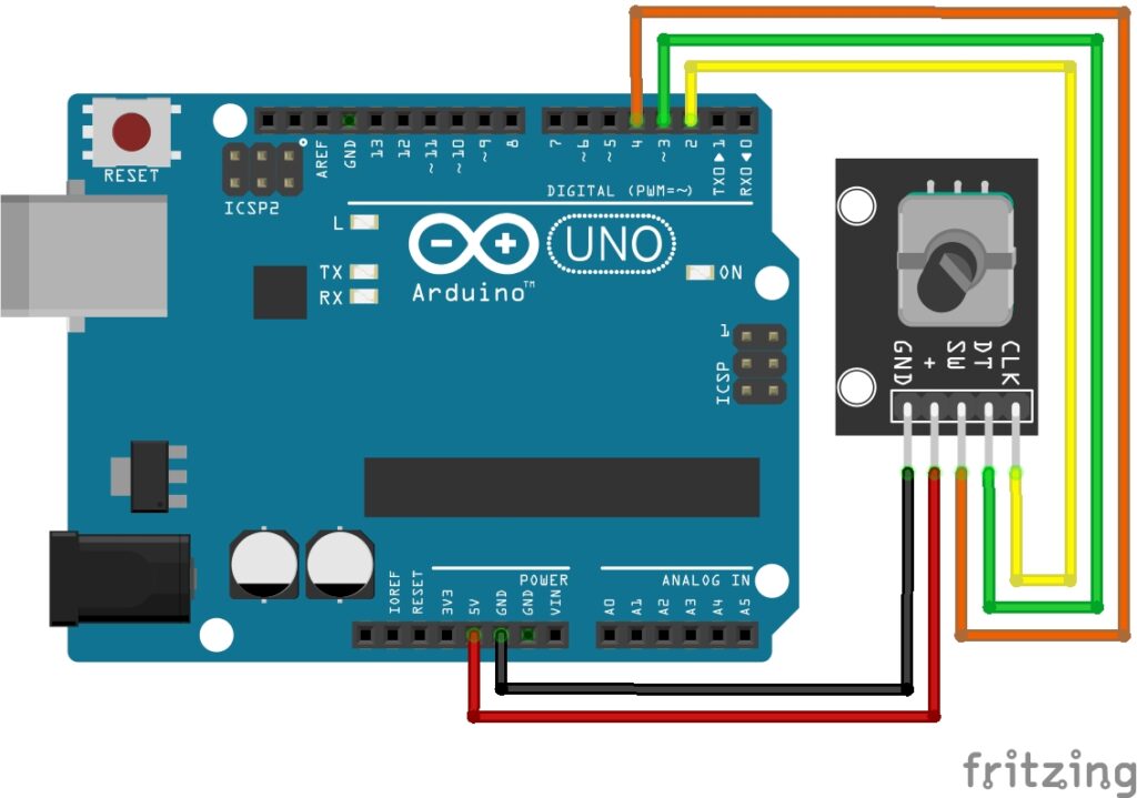
Pin Configuration
Integrating the Rotary Encoder with an Arduino is fairly simple. The Connections are as follows:
- GND on the Rotary Encoder to GND on the Arduino.
- + on Rotary Encoder to 5V on the Arduino.
- SW on the Rotary Encoder to Digital pin 4 on the Arduino.
- DT on the Rotary Encoder to Digital pin 3 on the Arduino.
- CLK on the Rotary Encoder to Digital pin 2 on the Arduino.
Pin labels may vary.
Appreciation to flaix for creating this fritzing part. You can find this module to create your own fritzing diagrams here: KY-040 Rotary Encoder breakout board part
Arduino Code Example
const int encoderPinA = 2;
const int encoderPinB = 3;
const int switchPin = 4;  // Assuming SW pin is connected to digital pin 4
volatile int encoderPos = 0;

void setup() {
  pinMode(encoderPinA, INPUT);
  pinMode(encoderPinB, INPUT);
  pinMode(switchPin, INPUT_PULLUP);  // Assuming the switch pin is pulled up
  attachInterrupt(digitalPinToInterrupt(encoderPinA), updateEncoder, CHANGE);
  Serial.begin(9600);
}

void loop() {
  // Your main code here

  // Print current encoder position
  Serial.print("Encoder Position: ");
  Serial.println(encoderPos);

  // Check switch state
  if (digitalRead(switchPin) == LOW) {
    Serial.println("Switch pressed!");
  }
}

void updateEncoder() {
  int A = digitalRead(encoderPinA);
  int B = digitalRead(encoderPinB);

  if (A != B) {
    encoderPos++;
  } else {
    encoderPos--;
  }

  // Additional logic based on encoder position
  Serial.print("Encoder Direction: ");
  Serial.println((A != B) ? "Clockwise" : "Counterclockwise");
}
Breaking Down the Code
Variables Declaration
const int encoderPinA = 2;andconst int encoderPinB = 3;: These variables store the pin numbers to which the encoder’s A and B output pins are connected, respectively.const int switchPin = 4;: This variable stores the pin number to which the switch pin of the encoder is connected.volatile int encoderPos = 0;: This variable stores the current position of the rotary encoder. Thevolatilekeyword indicates that the variable can be modified asynchronously by hardware interrupt routines.
Setup Function
pinMode(encoderPinA, INPUT);andpinMode(encoderPinB, INPUT);: These lines configure the pins connected to the encoder’s A and B output signals as input pins.pinMode(switchPin, INPUT_PULLUP);: This line configures the switch pin of the encoder as an input pin with a pull-up resistor enabled.attachInterrupt(digitalPinToInterrupt(encoderPinA), updateEncoder, CHANGE);: This line attaches an interrupt to the encoder’s A pin. Whenever the state of this pin changes (rising or falling edge), theupdateEncoder()function will be called.
Loop Function
Serial.print("Encoder Position: ");andSerial.println(encoderPos);: These lines print the current position of the encoder to the serial monitor.if (digitalRead(switchPin) == LOW) { Serial.println("Switch pressed!"); }: This condition checks if the switch pin of the encoder is pressed (LOW). If so, it prints a message to the serial monitor indicating that the switch is pressed.
Update Encoder Function
- This function is called whenever there is a change in the state of the encoder’s A pin.
int A = digitalRead(encoderPinA);andint B = digitalRead(encoderPinB);: These lines read the current states of the encoder’s A and B pins, respectively.if (A != B) { encoderPos++; } else { encoderPos--; }: This block of code determines the direction of rotation based on the states of the A and B pins. If A and B are different, it indicates clockwise rotation and incrementsencoderPos. If they are the same, it indicates counterclockwise rotation and decrementsencoderPos.Serial.print("Encoder Direction: ");andSerial.println((A != B) ? "Clockwise" : "Counterclockwise");: These lines print the direction of rotation (clockwise or counterclockwise) to the serial monitor.
Concepts
Interrupts
Interrupts are used to trigger the updateEncoder function whenever there is a change on encoderPinA. This ensures that the rotary encoder’s position is updated in real-time.
Pull-Up Resistor
The internal pull-up resistor is enabled for the switch pin to ensure a default HIGH state when the switch is not pressed. When the switch is pressed, it connects to ground, resulting in a LOW state.
Switch State Check
The code checks the state of the push-button switch using digitalRead(switchPin) to determine if it is pressed or not.
Encoder Position Update
The encoderPos variable is updated based on the direction of rotation, allowing the program to keep track of the current position of the rotary encoder.
Serial Monitoring
Serial communication is utilized to print information (encoder position, switch state) to the Serial Monitor for observation and debugging.
Understanding these concepts will help you modify the code according to your specific requirements or integrate it into larger projects.
Applications and Usage Scenarios
User Interface Controls
Rotary encoders are often used in user interface controls for devices such as audio equipment, digital radios, and amplifiers. They allow users to adjust volume, change frequencies, or scroll through menu options.
Rotational Position Sensing
In robotics and automation, rotary encoders are used to monitor the position of rotating components, such as wheels or joints. This information is crucial for accurate control and feedback in robotic systems.
Machine Tool Control
In CNC (Computer Numerical Control) machines and milling equipment, rotary encoders provide feedback on the position of cutting tools, enabling precise control of machining processes.
HVAC Systems
Rotary encoders can be used in heating, ventilation, and air conditioning (HVAC) systems to monitor the position of dampers or control valves, optimizing airflow and temperature regulation.
Printers and Plotters
In printers and plotters, rotary encoders help track the movement of print heads or paper, ensuring precise positioning and alignment during the printing process.
Camera Gimbal Control
In photography and videography, rotary encoders are used in camera gimbals to provide smooth and accurate control over the orientation of the camera.
Consumer Electronics
Many consumer electronics devices, such as digital cameras, gaming controllers, and home appliances, use rotary encoders for user input and control.
Automotive Applications
Rotary encoders can be found in automotive applications for monitoring the position of the steering wheel, throttle, or other rotating components. They play a role in vehicle stability control and other safety systems.
Medical Devices
Rotary encoders are used in medical devices for precise control of equipment such as surgical robots, diagnostic machines, and imaging devices.
Aerospace and Aviation
In aircraft and spacecraft, rotary encoders are utilized for position feedback in various systems, including control surfaces, navigation equipment, and avionics.
Industrial Automation
Rotary encoders play a vital role in industrial automation systems, providing feedback for the control of motors, conveyors, and other rotating machinery.
Virtual Reality (VR) Controllers
VR controllers often incorporate rotary encoders to enable users to interact with virtual environments by rotating or adjusting virtual objects.
Conclusion
In this sensors and modules guide, we explained the functionality of the Rotary Encoder Module, exploring its working principles, and demonstrating how to interface it with an Arduino for practical applications. The use of rotary encoders extends across a diverse range of applications, showcasing their adaptability and precision in monitoring rotational motion. From enhancing user interface controls in audio devices to providing critical position feedback in robotics and automation, rotary encoders contribute to the seamless operation of various systems.
Discover the endless possibilities for Arduino projects with more of our Sensors and Modules guides.
