


Welcome to the World of Sensors and Modules with Arduino!
The DS1307 Real Time Clock Module (RTC) is a compact and reliable device designed to keep accurate time in various applications. In this sensors and modules guide, we’ll explore its working principle, key features, applications, and how it can enhance your Arduino projects.
If you’re new to Arduino, why not take a look at our Getting Started with Arduino guides. These guides are designed for beginners to learn the fundamental basics of Arduino programming.
How the Real Time Clock Module Works
The heart of an RTC module is a crystal oscillator, which generates a stable and accurate frequency that serves as a timekeeping reference. The RTC counts seconds by dividing the frequency from the crystal oscillator. This count is then translated into minutes, hours, days, and so on. It has an onboard battery ensuring that the RTC’s internal clock continues running, even if the main power source is temporarily disconnected. Communication with the Arduino is typically achieved through I2C, allowing for easy integration and data exchange.
Features and Specifications:
- Operating Voltage: 3.3V ~ 5V.
- Operating Temperature: 0C ~ 70C.
- High Precision Timekeeping: RTC modules use crystal oscillators to maintain accurate timekeeping, often with precision down to the second.
- Calendar Functionality: Beyond timekeeping, RTC modules often include calendar features, providing day, date, month, and year information.
- Alarms and Timers: RTC modules may support programmable alarms and timers, enabling users to schedule events or trigger actions based on time.
- I2C Communication: The DS1307 communicates with the Arduino through the I2C (Inter-Integrated Circuit) protocol. This allows for seamless data exchange and configuration.
- Square Wave Output: The SQW (Square Wave) pin provides a fixed-frequency square wave, typically set at 1Hz. This feature can be harnessed for time-triggered events or simple clock displays.
- Battery Backup: The module often includes a small coin cell battery. This ensures that even during power interruptions, the DS1307 can retain timekeeping functionality.
- Compatibility: This module is also compatible with other devices like the Raspberry Pi, ESP32, and ESP8266 etc…
Necessary Equipment:
- Arduino (e.g., Arduino Uno)
- DS-1307 RTC module
- Jumper wires
- Breadboard (optional)
Pin Configuration
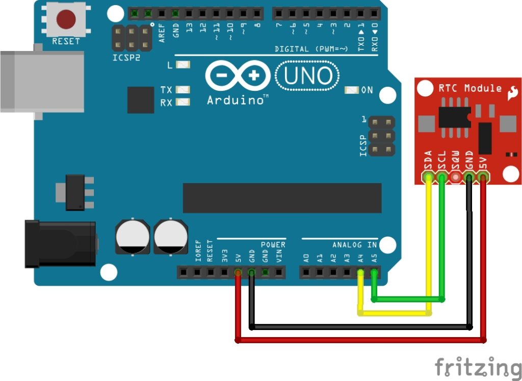
Connecting the RTC Module to an Arduino is fairly simple. The connections are as follows:
- VCC on the Real Time Clock Module to 5V on the Arduino.
- GND on the Real Time Clock Module to GND on the Arduino.
- SDA on the Real Time Clock Module to A4 on the Arduino.
- SCL on the Real Time Clock Module to A5 on the Arduino.
- SQW (optional) on the Real Time Clock Module to a Digital pin 2 on Arduino.
Installing the Real Time Clock Module Library
To use the RTC module with your Arduino projects, you’ll need to install the specific RTC library for your RTC module. Here’s how to install it:
- Open the Arduino IDE on your computer.
- Go to “Sketch” in the menu bar, then select “Include Library” and then “Manage Libraries…”
- In the Library Manager, you’ll find a search bar in the upper-right corner.
- Type “RTClib” into the search bar.
- Look for the “RTClib” library by Adafruit. Note that there might be multiple versions available, but you can usually go with the latest stable version.
- Click on the entry for the “RTClib” library.
- On the right side, you’ll see an “Install” button. Click on it.
- The Arduino IDE will download and install the RTClib library.
- Once the installation is complete, close the Library Manager.
This library works well with the Real Time Clock Module found in the Elegoo 37 Sensor Kit V2.
Arduino Code Example
#include <Wire.h>
#include <RTClib.h>

RTC_DS1307 rtc;

void setup() {
  Serial.begin(9600);

  if (!rtc.begin()) {
    Serial.println("Couldn't find RTC");
    while (1);
  }

  rtc.adjust(DateTime(F(__DATE__), F(__TIME__)));
}

void loop() {
  DateTime now = rtc.now();

  Serial.print(now.year(), DEC);
  Serial.print('/');
  Serial.print(now.month(), DEC);
  Serial.print('/');
  Serial.print(now.day(), DEC);
  Serial.print(" ");
  Serial.print(now.hour(), DEC);
  Serial.print(':');
  Serial.print(now.minute(), DEC);
  Serial.print(':');
  Serial.print(now.second(), DEC);
  Serial.println();

  delay(1000);
}
Breaking Down the Code
Library Includes
- Wire.h: This library provides functions to communicate with devices over the I2C bus.
- RTClib.h: This library is specific to RTC modules and provides functions to interact with Real-Time Clock modules, such as DS1307.
RTC Initialization
- An instance of the
RTC_DS1307class is created, representing the DS1307 RTC module.
Setup Function
- Serial.begin(9600): Initializes serial communication at a baud rate of 9600 for communication with the Serial Monitor.
- rtc.begin(): Initializes communication with the RTC module. If the RTC module is not found, it prints an error message and enters an infinite loop.
- rtc.adjust(DateTime(F(DATE), F(TIME))): Sets the initial date and time on the RTC module using the compilation date and time of the sketch.
Loop Function
- rtc.now(): Retrieves the current date and time from the RTC module and stores it in the
nowvariable of typeDateTime. - Serial.print(…): Prints the individual components of the date and time to the Serial Monitor.
- delay(1000): Introduces a delay of 1000 milliseconds (1 second) before the next iteration of the loop.
The code initializes communication with the RTC module, sets the initial date and time, and continuously reads and prints the current date and time to the Serial Monitor in a loop with a one-second delay between readings. The Serial Monitor provides a real-time display of the RTC’s output.
How to Adjust and Use the Real Time Clock Module
- Setting Time: Set the initial time on the RTC module using the
adjustmethod in your Arduino code. - Reading Time: Use the
nowmethod to read the current date and time from the RTC module. - Battery Replacement: When replacing the main power source, the RTC continues running on the backup battery. Ensure the backup battery is functional for uninterrupted timekeeping.
- Visualizing Time: Utilize the Serial Monitor to observe the RTC module’s output and verify correct timekeeping.
The Real Time Clock Module SQW Pin
The RTC module has an SQW (Square Wave) pin that provides a simple square wave output.
Here’s more information about the SQW pin on the RTC Module:
RTC Module SQW Pin Features:
- Square Wave Output: The primary function of the SQW pin on the RTC Module is to output a square wave signal. This signal has a fixed frequency of 1Hz.
- Fixed Frequency: Unlike the DS3231 RTC, the DS1307 RTC has a fixed square wave frequency, and you cannot configure it to output square waves at different frequencies. The frequency is set to 1Hz, which means it produces one cycle per second.
- Configuring SQW Pin Mode: While you can’t change the frequency, you can configure the SQW pin mode using the
writeSqwPinModemethod in your Arduino code. The available modes include enabling the 1Hz square wave output or setting the SQW pin to a low level.
Wiring SQW Pin:
- Connect the SQW pin on the DS1307 module to a digital input pin on your Arduino if you want to read the square wave output or if you plan to use it for any specific purpose.
Use Cases:
- Simple Clock Display: Use the 1Hz square wave output for a simple clock display with blinking seconds.
- Time-Based Triggers: Utilize the fixed frequency square wave for time-triggered actions in your Arduino project.
- Pulse Counter: Count the pulses generated by the SQW pin for applications where a simple counter is needed.
Remember that the SQW pin on the DS1307 RTC provides a straightforward 1Hz square wave output, and its functionality is more basic compared to the DS3231. If your application requires more flexibility or different square wave frequencies, the DS3231 might be a better choice.
Applications and Usage Scenarios
Clock Displays
Use Real Time Clock modules in projects that require a real-time clock display, such as digital clocks or time-sensitive data logging.
Data Logging
Ideal for timestamping data in data logging applications where it’s crucial to record the exact time when certain events occur.
Automation Systems
Integrate Real Time Clock modules into home automation systems to schedule and trigger events at specific times.
Security Systems
Enhance security systems with time-sensitive functionalities like scheduled arming or disarming.
Conclusion
In this sensors and modules guide, we explained the functionality of the Real Time Clock Module, exploring its working principles, and demonstrating how to interface it with an Arduino for practical applications. Whether you’re building a digital clock, a data logger with timestamped records, or an automation system with scheduled events, the Real Time Clock Module is your steadfast companion. The inclusion of a backup battery ensures uninterrupted timekeeping, making sure your projects stay synchronized even when the main power takes a temporary break.
Discover the endless possibilities for Arduino projects with more of our Sensors and Modules guides.

