


Welcome to the World of Sensors and Modules with Arduino!
The RGB LED Module brings vibrant illumination to your Arduino projects, allowing you to paint your creations with an array of dazzling colors. Whether you’re designing mood lighting for your room, crafting interactive displays, or adding visual feedback to your projects, RGB LED Modules offer endless possibilities for creative expression. In this sensors and modules guide, we’ll explore the RGB LED Modules working principle, key features, applications, and how to integrate it with your Arduino projects.
If you’re new to Arduino, why not take a look at our Getting Started with Arduino guides. These guides are designed for beginners to learn the fundamental basics of Arduino programming.
How the RGB LED Module Works
RGB LED modules consist of three separate LEDs, one for each color channel (red, green, and blue), integrated into a single package. By adjusting the intensity of each color channel using PWM signals, users can create a wide spectrum of colors, including white by mixing all three colors at full intensity.
Features and Specifications:
- Color Mixing: Combines red, green, and blue (RGB) light to produce a variety of colors.
- Operating Voltage: 3V ~ 5V.
- Control: Each color channel (red, green, and blue) can be controlled independently using pulse-width modulation (PWM) signals from an Arduino.
- Variants: Available in various form factors, including individual LED modules and integrated RGB LED strips.
- Compatibility: This module is also compatible with other devices like the Raspberry Pi, ESP32, and ESP8266 etc…
The operating voltage for each color of the LEDs in an RGB LED module typically depends on the specific type of LEDs used. However, common RGB LEDs usually have similar voltage requirements for each color channel. Here’s a general guideline for each color channel in RGB LEDs:
- Red LED:
- Operating Voltage: 1.8 to 2.1V
- Color: 620-625 nm
- Brightness: @ ~20mA: 600-800 mcd
- Green LED:
- Operating Voltage: 3.0 to 3.2V
- Color: 520-525 nm
- Brightness: @ ~20mA: 1500-2000mcd
- Blue LED:
- Operating Voltage: 3.0 to 3.2V
- Color: 465-470 nm
- Brightness: @ ~20mA: 800-1000 mcd
It’s important to note that these are values are from the RGB LED Module supplied with the Elegoo 37 Sensor Kit V2 datasheet. The actual operating voltage of your RGB LED may vary depending on the specific LED model, manufacturer.
Necessary Equipment:
- Arduino (e.g., Arduino Uno)
- RGB LED Module
- 220Ω Resistor x3
- Jumper wires
- Breadboard
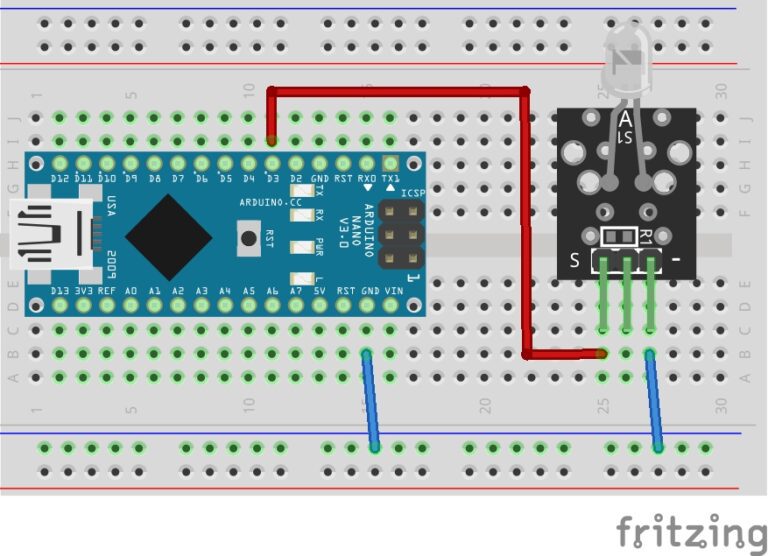
Some RGB LED Modules already have the resistors soldered onto the board.
Pin Configuration
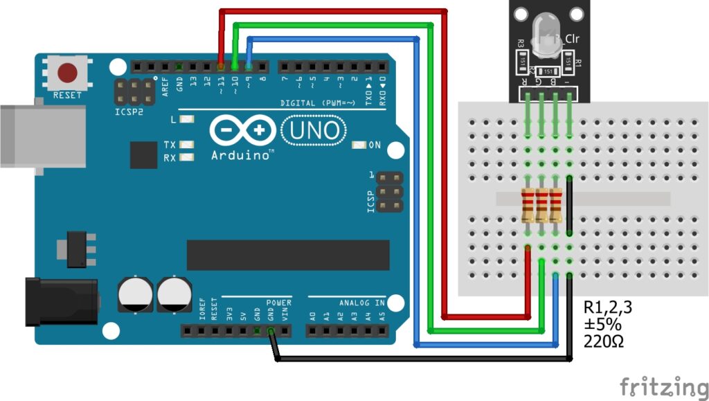
Connecting the RGB LED Module to an Arduino is fairly simple. The connections are as follows:
- B on the RGB LED Module to Digital pin 9 on the Arduino.
- G on the RGB LED Module to Digital pin 10 on the Arduino.
- R on the RGB LED Module to Digital pin 11 on the Arduino.
- – on the RGB LED Module to GND on the Arduino.
Pin labels may vary.
We connect the RGB LED Module to PWM pins on the Arduino. These pins can be identified by the (~) symbol next to their corresponding numbers. This is so we can adjust the intensity level (0-255) for each color.
Important: If you’re using a standard RGB LED or your module does not have current limiting resistors soldered to the module, you will need to add resistors between each of the color pins on your circuit to avoid permanent damage to the LEDs. The operating voltage of each color is slightly different, we can use different value resistors to make the color intensity the same across the colors or you can adjust the intensity values in the code. I have kept the resistors the same value in this guide to keep it as simple as possible.
KY-016 RGB full color LED Module Fritzing Part is created by arduinomodules.info and published under Creative Commons Attribution-ShareAlike 4.0 International license
Arduino Code Example
// Define the pins for the SMD RGB Module
const int redPin = 11;    // Connect the red pin to this PWM pin
const int greenPin = 10;  // Connect the green pin to this PWM pin
const int bluePin = 9;   // Connect the blue pin to this PWM pin

void setup() {
  // Set the RGB pins as outputs
  pinMode(redPin, OUTPUT);
  pinMode(greenPin, OUTPUT);
  pinMode(bluePin, OUTPUT);
}

void loop() {
  // Set RGB LED to red color
  setColor(255, 0, 0); // Full intensity red, no green, no blue
  delay(1000); // Stay red for 1 second

  // Set RGB LED to green color
  setColor(0, 255, 0); // No red, full intensity green, no blue
  delay(1000); // Stay green for 1 second

  // Set RGB LED to blue color
  setColor(0, 0, 255); // No red, no green, full intensity blue
  delay(1000); // Stay blue for 1 second
}

// Function to set the RGB LED color
void setColor(int red, int green, int blue) {
  analogWrite(redPin, red);     // Set intensity of red LED
  analogWrite(greenPin, green); // Set intensity of green LED
  analogWrite(bluePin, blue);   // Set intensity of blue LED
}
Breaking Down the Code
Pin Definitions
- The code begins by defining three integer constants
redPin,greenPin, andbluePin, which represent the PWM pins connected to the red, green, and blue channels of the RGB LED Module, respectively. - These pins are where the Arduino sends PWM signals to control the intensity of each color channel.
Setup Function
- The
pinMode()function is used to configure theredPin,greenPin, andbluePinas output pins. This prepares them to receive PWM signals to control the RGB LED.
Loop Function
- The code repeatedly sets the RGB LED to three different colors: red, green, and blue, with each color displayed for 1 second.
- For each color:
- The
setColor()function is called with specific intensity values for red, green, and blue, determined by the arguments passed to the function. - A
delay()of 1000 milliseconds (1 second) is added to keep the LED in that color for the specified duration.
- The
Color Function
- The
setColor()function is responsible for setting the intensity of each color channel of the RGB LED. - It takes three integer arguments:
red,green, andblue, representing the intensity of each color channel. The values range from 0 (off) to 255 (full intensity). - Inside the function:
analogWrite()is used to send PWM signals to theredPin,greenPin, andbluePinto control the intensity of each color channel.- The intensity values passed to
analogWrite()determine the brightness level of each color.
Applications and Usage Scenarios
Decorative Lighting
The RGB is commonly used for creating colorful lighting effects in DIY projects, artworks, and decorative displays.
Indicators and Signage
It can serve as indicators or status lights in various applications, such as signage, control panels, or user interfaces.
Visual Feedback
By changing colors based on sensor inputs or system status, the module provides visual feedback to users in interactive projects.
Mood Lighting
It’s ideal for mood lighting setups, allowing users to adjust the ambiance and atmosphere by selecting different colors.
Conclusion
In this sensors and modules guide, we explain that the RGB LED Module offers a compact, and versatile solution for adding vibrant and dynamic lighting effects to Arduino projects. By understanding its features, operation, and integration with Arduino, users can unleash their creativity and illuminate their projects with an array of captivating colors.
Discover the endless possibilities for Arduino projects with more of our Sensors and Modules guides.
