


Welcome to the World of Sensors and Modules with Arduino!
The dual axis joystick module is a versatile input device that provides two-dimensional control, allowing users to manipulate objects in both the X and Y axes. In Arduino projects, these modules are commonly used to interact with games, control robotic systems, or navigate through user interfaces. In this sensors and modules guide, we’ll explore its working principle, key features, applications, and how it can enhance your Arduino projects.
If you’re new to Arduino, why not take a look at our Getting Started with Arduino guides. These guides are designed for beginners to learn the fundamental basics of Arduino programming.
How the Dual Axis Joystick Module Works
Joystick modules use potentiometers to measure the position of the joystick in both the X and Y axes.
Two potentiometers, one for the X-axis and one for the Y-axis, are mounted perpendicular to each other. These potentiometers create variable resistances based on the joystick’s position. As the joystick moves, the potentiometers divide the input voltage, producing analog output signals proportional to the joystick’s position along each axis. The analog output signals from the potentiometers are read by the Arduino, providing information about the joystick’s position in both axes.
Features and Specifications:
- Operating Voltage: 3.3V ~ 5V
- Dual-Axis Control: Joystick modules offer control in two dimensions: horizontal (X-axis) and vertical (Y-axis). This enables precise and intuitive manipulation.
- Analog Output: They provide analog output signals proportional to the joystick’s position, making them suitable for applications that require smooth and continuous control.
- Built-in Button(s): Many joystick modules include one or more built-in buttons, adding an extra layer of functionality for project interaction.
- Compact Design: Joystick modules are compact and ergonomic, making them easy to integrate into a variety of projects.
- Compatibility: This module is also compatible with other devices like the Raspberry Pi, ESP32, and ESP8266 etc…
Necessary Equipment:
- Arduino (e.g., Arduino Uno)
- Dual Axis Joystick Module
- Jumper wires
- Breadboard (optional)
Pin Configuration
Connecting the dual axis joystick module to an Arduino is fairly simple. The connections are as follows:
- GND on the Dual Axis Joystick Module to GND on the Arduino.
- 5V on the Dual Axis Joystick Module to 5V on the Arduino.
- VRx on the Dual Axis Joystick Module to analog pin A0 on the Arduino.
- VRy on the Dual Axis Joystick Module to analog pin A1 on the Arduino.
- SW on the Dual Axis Joystick Module to Digital pin 2 on the Arduino.
Pin labels may vary.
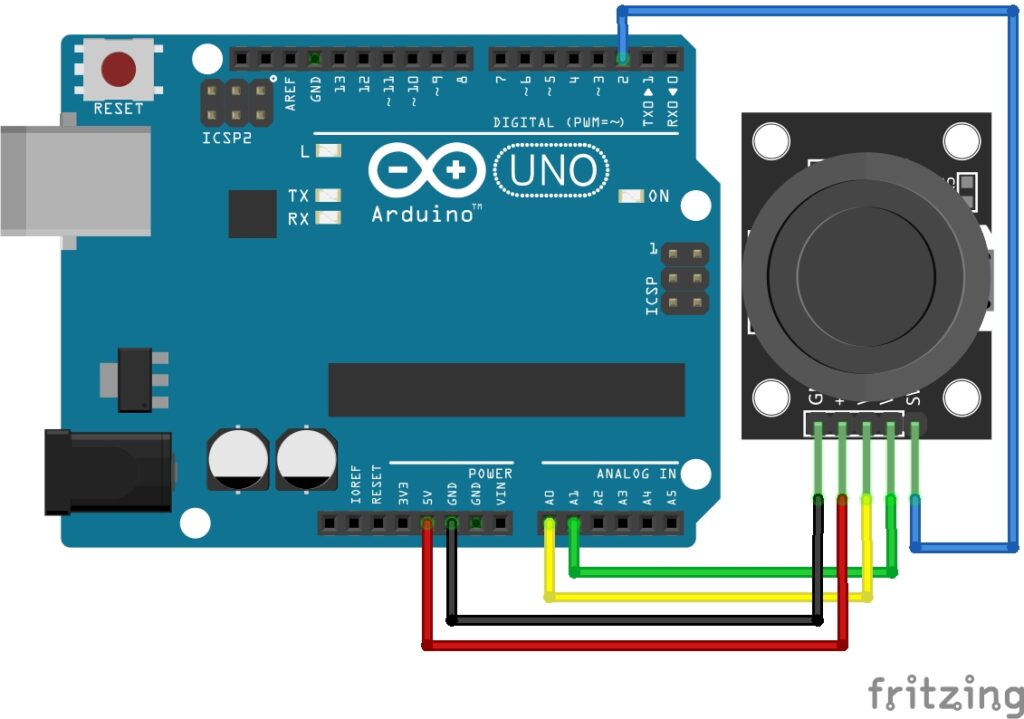
KY-023 Dual Axis Joystick Module Fritzing Part is created by arduinomodules.info and published under Creative Commons Attribution-ShareAlike 4.0 International license
Arduino Code Example
// Define the pins to which the joystick module is connected
const int xAxisPin = A0;  // Connect the X-axis pin of the joystick to this analog pin
const int yAxisPin = A1;  // Connect the Y-axis pin of the joystick to this analog pin
const int switchPin = 2;  // Connect the SW pin of the joystick to this digital pin

void setup() {
  // Initialize the Serial communication for debugging
  Serial.begin(9600);

  // Set the switch pin as input pullup for stability
  pinMode(switchPin, INPUT_PULLUP);
}

void loop() {
  // Read the analog values from the X and Y axes of the joystick
  int xAxisValue = analogRead(xAxisPin);
  int yAxisValue = analogRead(yAxisPin);

  // Read the state of the switch
  int switchState = digitalRead(switchPin);

  // Print the X and Y axis values and switch state to the Serial Monitor
  Serial.print("X-axis: ");
  Serial.print(xAxisValue);
  Serial.print("   Y-axis: ");
  Serial.print(yAxisValue);
  Serial.print("   Switch: ");
  Serial.println(switchState);

  // Add a short delay for stability
  delay(500);
}
Breaking Down the Code
Pin Declaration
- Constants are defined for the analog pins connected to the X and Y axes of the joystick (
xAxisPinandyAxisPin). - A constant is defined for the digital pin connected to the joystick switch (
switchPin).
Setup Function
- The
setupfunction is executed once when the Arduino starts. - Serial communication is initialized at a baud rate of 9600 for debugging purposes.
pinMode(switchPin, INPUT_PULLUP);configures the switch pin as an input with a pull-up resistor, providing a stable state when the switch is not pressed.
Loop Function
- The
loopfunction is executed repeatedly. int xAxisValue = analogRead(xAxisPin);reads the analog value from the X-axis pin of the joystick and stores it inxAxisValue.int yAxisValue = analogRead(yAxisPin);reads the analog value from the Y-axis pin of the joystick and stores it inyAxisValue.int switchState = digitalRead(switchPin);reads the state of the switch and stores it inswitchState.- The X and Y axis values, along with the switch state, are printed to the Serial Monitor.
delay(500);adds a short delay of 500 milliseconds between iterations for stability.
Applications and Usage Scenarios
Gaming Controllers
Joystick modules are commonly used as input devices for creating gaming controllers in Arduino projects.
Robotic Control
They serve as effective control interfaces for robotic systems, providing a convenient way to steer and navigate.
Camera Gimbal Control
Joystick modules are employed to control camera gimbals, allowing users to pan and tilt the camera smoothly.
Menu Navigation
In user interface projects, joystick modules facilitate menu navigation and selection.
Arduino Gaming Console
Develop an Arduino-based gaming console using a joystick module for directional control and buttons for gameplay.
Remote-Controlled Robot
Create a remote control for a robot using a joystick module to precisely control its movements.
Camera Gimbal System
Implement a camera gimbal system where a joystick module controls the orientation of the camera.
Conclusion
In this sensors and modules guide, we explained the functionality of the Dual Axis Joystick Module, exploring its working principles, and demonstrating how to interface it with an Arduino for practical applications. Joystick modules offer a tactile and versatile means of user input in Arduino projects. Understanding their features, working principles, and applications empowers electronics enthusiasts to incorporate precise control into a wide range of projects. Whether you’re navigating a menu, steering a robot, or controlling a camera, joystick modules provide an intuitive and engaging interface for your projects.
Discover the endless possibilities for Arduino projects with more of our Sensors and Modules guides.