

What is a Tactile Switch?
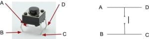
Tactile switches, often referred to as “tac switches” or “tact switches,” are commonly used in electronic circuits and can be programmed with an Arduino microcontroller to perform various tasks or trigger actions when the button is pressed. The tac switch, like any normal switch, can be used to complete a circuits connection. In the image below, when the button is pressed A and B are connected, D and C are connected, this is the correct direction the switch works. When the button is released, the circuit is broken again. The tac switch can be used for all kinds of Arduino projects and this guide will show you how to program tactile switches with Arduino.
How to Program Tactile Switches with Arduino
Here’s a step-by-step guide on how to program tactile switches with Arduino:
Components You’ll Need:
- Arduino board (e.g., Arduino Uno, Arduino Nano, etc.)
- Tactile switch(s)
- Breadboard and jumper wires
- Resistors (optional, for pull-up or pull-down configurations)
Steps:
Wire up the Tactile Switch:
Connect the tactile switch to the Arduino. Tactile switches usually have four pins (two on each side). Wire them up as follows:
- Connect one side of the switch (either pair of pins) to a digital input pin on the Arduino.
- Connect the other side of the switch to either GND (ground) or 5V on the Arduino, depending on whether you want a pull-up or pull-down configuration.
If you connect it to GND, you’ll need to enable the internal pull-up resistor on the Arduino. If you connect it to 5V, you can directly read the switch state.
Write the Arduino Code:
Here’s a basic example of Arduino code to detect when the switch is pressed:
const int switchPin = 2; // Change this to the pin you connected the switch to

void setup() {
  pinMode(switchPin, INPUT_PULLUP); // Enable the internal pull-up resistor
  Serial.begin(9600); // Initialize serial communication for debugging
}

void loop() {
  int switchState = digitalRead(switchPin); // Read the state of the switch
  if (switchState == LOW) { // When the button is pressed
    Serial.println("Button pressed!");
    // Add your code here for what to do when the button is pressed
    delay(100); // Add a small delay to debounce the switch
  }
}
In this code, we use the digitalRead() function to check the state of the switch connected to the switchPin. When the button is pressed and the switch connects the pin to ground (LOW), it prints “Button pressed!” to the serial monitor and performs any additional actions you specify.
Upload and Test:
Upload the code to your Arduino board using the Arduino IDE and open the serial monitor. When you press the tactile switch, you should see “Button pressed!” printed in the serial monitor.
Add Actions:
Modify the code inside the if (switchState == LOW) block to perform specific actions when the button is pressed. For example, you could control an LED, toggle a relay, or send a signal to another device.
That’s the basic process of programming tactile switches with Arduino. You can expand on this by implementing more complex logic or integrating the switch into larger projects.
Let's Build!
The LED Toggle Switch
The Code:
Here I will show you how to create a basic Toggle Switch which will simply turn an LED on and then off again. Copy the following code to a new sketch in your IDE:
int ledPin = 5;
int buttonON = 9;
int buttonOFF = 8;
void setup(){
  pinMode(ledPin, OUTPUT);
  pinMode(buttonON, INPUT_PULLUP);
  pinMode(buttonOFF, INPUT_PULLUP);
}
void loop(){
  if (digitalRead(buttonON) == LOW){
    digitalWrite(ledPin, HIGH);
  }
  if (digitalRead(buttonOFF) == LOW){
    digitalWrite(ledPin, LOW);
  }
}
Study the code above and you will notice a new addition to the code INPUT_PULLUP you can read more about Arduino’s internal resistors here: Internal Resistors but we will be learning about them soon.
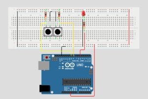
The Circuit:
Now, assemble your components the same way as in the image below. Use a 220 Ohm resistor to protect your LED.

Upload the Code:
Once upload is complete, press the buttons. The Pull-Up keeps a constant HIGH so when the button is pressed, the button pin reads LOW, when the button is LOW, our command is then executed, and the LED is either turned on or off depending which button is pressed.
The LED Dimmer
The Code:
Study the code below. Brightness is set to 0, here we are going to use PWM to control the brightness of an LED by incrementing it by 20 or decrementing it by 20. Remember digitalWrite is either HIGH or LOW, a 1 or a 0, so here we are going to use analogWrite on a digital pin so we can use 0-255. 0 would be fully off, 255 would be fully on, 125 would be somewhere in between.
int buttonUP=9;
int buttonDOWN=8;
int buttonVal1;
int buttonVal2;
int Brightness=0; //0-255
int LED=5;

void setup() {
  Serial.begin(9600);
  pinMode(LED,OUTPUT);
  pinMode(buttonUP,INPUT);
  pinMode(buttonDOWN,INPUT);
}

void loop() {
  buttonVal1=digitalRead(buttonUP);
  Serial.println(buttonVal1);
  delay(200);
  if(buttonVal1==0){
    Brightness=Brightness+20;
    delay(20);
  }
  buttonVal2=digitalRead(buttonDOWN);
  Serial.println(buttonVal2);
  delay(200);
  if(buttonVal2==0){
    Brightness=Brightness-20;
    delay(20);
  }
  if(Brightness>255){
    Brightness=255;
    delay(20);
  }
  if(Brightness<0){
    Brightness=0;
    delay(20);
  }
  Serial.print("LED = ");
  Serial.print(Brightness);
  Serial.println(" Brightness");
  analogWrite(LED, Brightness);
  delay(500);
}
The Circuit:
Assemble your components in the same way as the image below, use 2 10k Ohm resistors for the button Pull-Ups, this keeps our readings at a constant HIGH. HIGH and LOW is binary, either it’s a 1 or it’s a 0. Use a 220 Ohm resistor to protect your LED as usual.
Upload the Code:
Upload the code to your Arduino board. Once uploaded open your serial monitor and press the buttons to see the results. To turn the LED fully on would take 13 button presses, and then once fully on, 13 button presses to turn it off again. Obviously 13×20=260 but we can only go to 255, so we create a condition, anything above 255 is 255, and anything below 0 is 0.
The RGB Color Changer
The Code:
This time we will be changing the LED for an RGB and adding another push button to the circuit so we can control the red, green and blue values of an RGB.
The code below might seem like a lot but this time we have to account for the red, green, and blue of the RGB so there is a lot of repetition. Simply copy and paste the code below to a new sketch in your IDE:
//Button Pins
int redUP=9;
int greenUP=10;
int blueUP=11;
//LED Pins
int RED=3;
int GREEN=5;
int BLUE=6;
//Button state
int redButtonVal;
int greenButtonVal;
int blueButtonVal;
int resetVal;
//Color Brightness
int redBright=0;
int greenBright=0;
int blueBright=0;
void setup() {
Serial.begin(9600);
pinMode(RED,OUTPUT);
pinMode(GREEN,OUTPUT);
pinMode(BLUE,OUTPUT);
pinMode(redUP,INPUT);
pinMode(greenUP,INPUT);
pinMode(blueUP,INPUT);
}
void loop() {
redButtonVal=digitalRead(redUP);
Serial.print("RED Button Val = ");
Serial.println(redButtonVal);
delay(200);
if(redButtonVal==0){
redBright=redBright+20;
delay(20);
}
if(redBright>255){
redBright=255;
delay(20);
}
if(redBright<0){
redBright=0;
delay(20);
}
Serial.print("RED Strength is = ");
Serial.println(redBright);
greenButtonVal=digitalRead(greenUP);
Serial.print("GREEN Button Val = ");
Serial.println(greenButtonVal);
delay(200);
if(greenButtonVal==0){
greenBright=greenBright+20;
delay(20);
}
if(greenBright>255){
greenBright=255;
delay(20);
}
if(greenBright<0){
greenBright=0;
delay(20);
}
Serial.print("GREEN Strength is = ");
Serial.println(greenBright);
blueButtonVal=digitalRead(blueUP);
Serial.print("BLUE Button Val = ");
Serial.println(blueButtonVal);
delay(200);
if(blueButtonVal==0){
blueBright=blueBright+20;
delay(20);
}
if(blueBright>255){
blueBright=255;
delay(20);
}
if(blueBright<0){
blueBright=0;
delay(20);
}
Serial.print("BLUE Strength is = ");
Serial.println(blueBright);
delay(200);
if(redButtonVal==0 && greenButtonVal==0){
redBright=0;
blueBright=0;
greenBright=0;
Serial.println("RESET");
delay(20);
}
analogWrite(RED, redBright);
analogWrite(GREEN, greenBright);
analogWrite(BLUE, blueBright);
delay(1000);
Serial.println("");
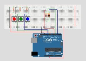
}The Circuit:
Assemble your components the exact same way as in the image below. Don’t panic if your push buttons are not red, green, and blue, I just made the image this way, the standard black switches will work just the same.
Upload the Code:
Now, upload the code to the Arduino board. Once uploaded open your serial monitor on the Arduino IDE. With every push off a button the brightness strength for its color increases by 20. An RGB is capable of producing over 16million different color variations. To reset the color strength to zero for all just press the left and middle button together.
Conclusion
Programming tactile switches with Arduino is a fundamental skill for building interactive electronic projects. By following the steps outlined above, you can easily detect button presses and trigger actions in response to user input. Tactile switches provide a versatile means of user interaction, and with a little creativity, you can incorporate them into a wide range of applications, from simple LED control to complex automation systems.
Study and make sure you understand the code for each of the projects we have covered in this guide. If you have any problems or don’t understand something, just ask and I’ll be happy to help.
Happy Tinkering!
Recommendations:
If you don’t already own any Arduino hardware, we highly recommend purchasing the Elegoo Super Starter Kit. This kit has everything you need to start programming with Arduino.
You can find out more about this kit here: Elegoo Super Starter Kit

