
Introduction to the Arduino Pins
As you start your Arduino journey, it’s important to learn about the different types of Arduino pins. Arduino boards have several pins, and each one has a specific job. In this lesson, we’ll explain Arduino UNO pins clearly, covering digital, analog, and special pins. By the end, you’ll know how to use these pins in your projects.
Types of Arduino Pins
Next, let’s dive deeper into the details of each pin type commonly found on Arduino boards.
Digital Pins
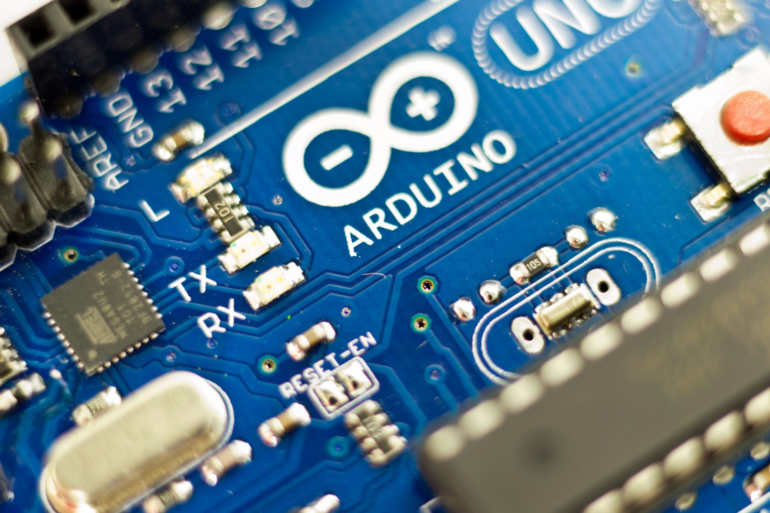
First, digital pins handle binary signals (HIGH or LOW, meaning 5V or 0V).
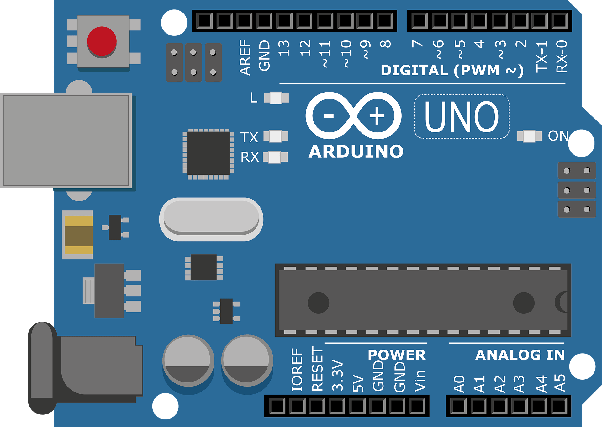
The Arduino Uno has 14 digital pins (labeled 0 to 13).
Additionally, 6 of these (pins 3, 5, 6, 9, 10, 11) can function as PWM (Pulse Width Modulation) pins for analog-like output, such as dimming LEDs.
Use these for components like buttons, LEDs, or digital sensors.
Analog Pins
Next, analog input pins read variable voltage levels (0V to 5V) and convert them to digital values (0 to 1023).
The Uno has 6 analog input pins (labeled A0 to A5).
For example, these are ideal for reading sensors like potentiometers or temperature sensors.
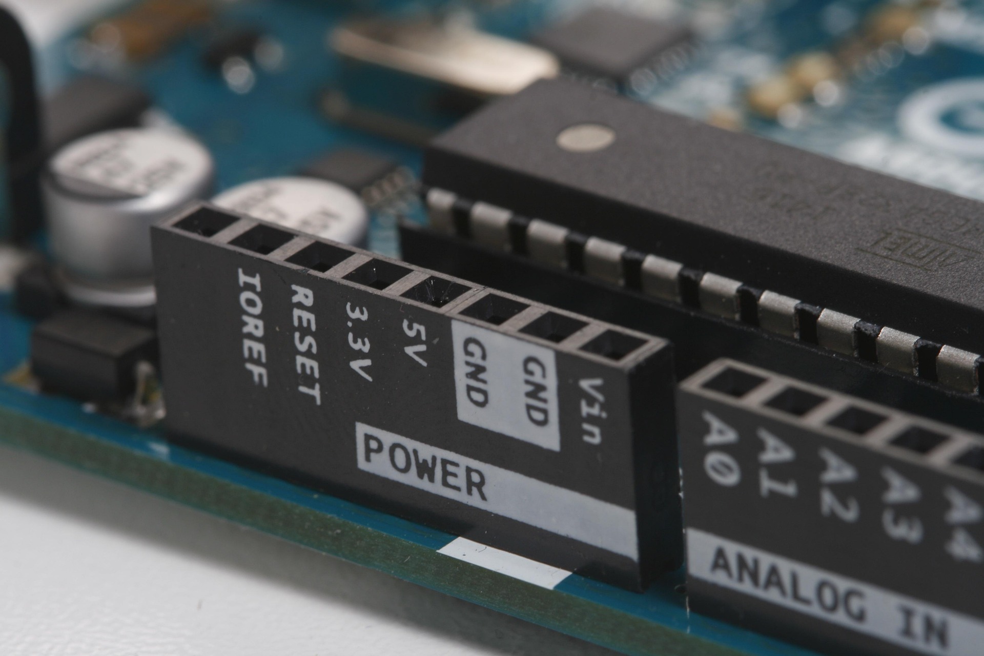
Power Pins
Additionally, power pins supply or receive power for the board and components.
Common pins include:
5V: Outputs 5V to power components.
3.3V: Outputs 3.3V for specific devices.
GND (Ground): Completes circuits; the Uno has multiple GND pins.
Vin: Supplies external voltage (e.g., from a battery) or outputs voltage when powered externally.
Special Arduino Pins
Finally, special Arduino pins have unique functions beyond standard input/output:
IOREF: Outputs the board’s operating voltage (5V on the Uno) to help shields match the correct logic level.
AREF: Sets the reference voltage (0–5V) for analog inputs, used with analogReference(EXTERNAL) for precise sensor readings.
ICSP Header: Used for programming the microcontroller or connecting shields.
Reset Pin: Resets the board when pulled LOW.
TX (pin 0) and RX (pin 1): Handle serial communication, like sending data to a computer.
External Interrupts (pins 2 and 3): Trigger special actions when signals change.
I2C (A4 as SDA, A5 as SCL): Support I2C communication for sensors or modules.
SPI (pins 10–13): Enable SPI communication for devices like SD card modules.
Tips:
First, some pins have multiple functions (e.g., analog pins A0–A5 can act as digital I/O if not used for analog input).
Next, always check the Arduino Uno pinout diagram for your specific board to confirm pin roles, as slight variations exist across Arduino models.
Finally, a simple way to remember which pins are SCL and SDA pins remember Serial Clock and Serial Data. Clock has 5 letters so its A5, Data has 4 letters so its A4.
Conclusion
Understanding these different types of pins and their capabilities is crucial for effectively using Arduino boards in your projects. Each type of pin has specific functions and applications, and mastering their use will enable you to create a wide range of electronic projects.
Happy tinkering!
Have any questions or want to share your projects? Connect with us on X/Twitter for more tips and inspiration!
Click on the button below if you’re ready to continue with the next lesson which is about Basic Components for the Arduino Uno.
