Arduino Analog Input and Output Pins
Related Articles
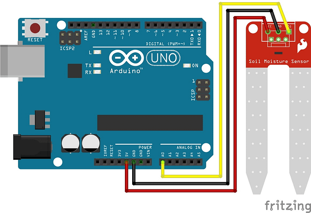
Soil Moisture Sensor with Arduino
Welcome to the World of Sensors and Modules with Arduino! The moisture sensor, also known as a soil moisture sensor,…
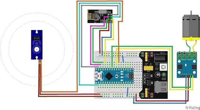
NRF24L01 Radio Controlled Arduino Project
Building our First Radio Controlled Arduino Project The NRF24L01 RF Module is a low-cost, high-performance 2.4GHz transceiver module widely used…
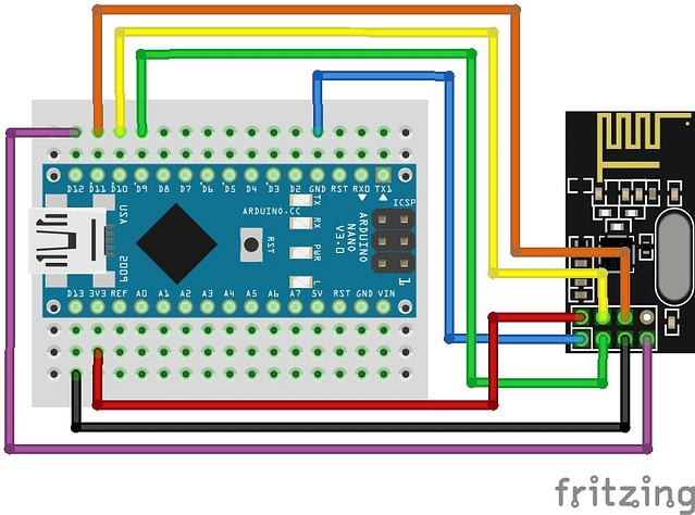
NRF24L01: Building your First Radio with Arduino
Welcome to the World of Sensors and Modules with Arduino! In this guide we will be building a basic transmitter…