

Welcome to the World of Sensors and Modules with Arduino!
The 5V Relay Module serves as crucial component in certain Arduino projects, enabling the control of high-voltage devices with the microcontroller’s low-voltage signals. While immensely useful, the handling of high-voltage equipment can pose risks, especially for inexperienced or young Arduino enthusiasts. To keep our less experienced readers safe, we have opted to use a 9V battery as the higher voltage power supply. In this sensors and modules guide, we’ll explore the features, working principles, and applications of relay modules when used with Arduino, while also emphasizing safety considerations for all readers.
If you’re new to Arduino, why not take a look at our Getting Started with Arduino guides. These guides are designed for beginners to learn the fundamental basics of Arduino programming.
How the Relay Module Works
Relay modules function as electrically operated switches that can be controlled by the Arduino. When the Arduino sends a signal to the relay module, the internal electromagnet activates, causing the switch to toggle between open and closed positions. This allows low-voltage signals from the Arduino to control high-voltage devices safely.
Features and Specifications
- TTL Control Signal: 5V
- AC Voltage: 50V Maximum
- DC Voltage: 75V Maximum
- Current: 10A Maximum
- Contact Type: NO (normally open) and NC (normally closed)
- Status Indicator: Onboard indication LED for Relays status
- Compatibility: This sensor is also compatible with other devices like the Raspberry Pi, ESP32, and ESP8266 etc…
Necessary Equipment:
- Arduino (e.g., Arduino Uno)
- 5V Relay Module
- 9V Battery
- LED
- 220Ω Resistor
- Jumper wires
- Breadboard (optional)
Understanding the 5V Relay Input and Output Pins
A 5V relay module typically consists of several input and output pins. Here’s a breakdown of the common input and output pins you might find on a standard 5V relay module:
Input Pins
- + (VCC or +5V): This pin is used to provide power to the relay module. It typically requires a 5V power supply to operate.
- – (GND or Ground): This pin is connected to the ground (0V) of the power supply.
- S (IN or Signal): This pin is used to control the relay. Applying a HIGH (5V) signal to this pin activates the relay, while a LOW (0V) signal deactivates it. This pin is usually connected to a digital output pin of a microcontroller (like Arduino).
Output Pins
- COM (Common): This is the common connection point of the relay switch. It’s typically connected to one end of the load (the device or circuit you want to control).
- NO (Normally Open): When the relay is not activated, this pin is not connected to COM. When the relay is activated (by applying a HIGH signal to the input pin), the connection between NO and COM is established, allowing current to flow through the load.
- NC (Normally Closed): When the relay is not activated, this pin is connected to COM. When the relay is activated, the connection between NC and COM is broken. This pin is often used for specific applications where the load needs to be powered off by default and powered on when the relay is activated.
Pin Configuration
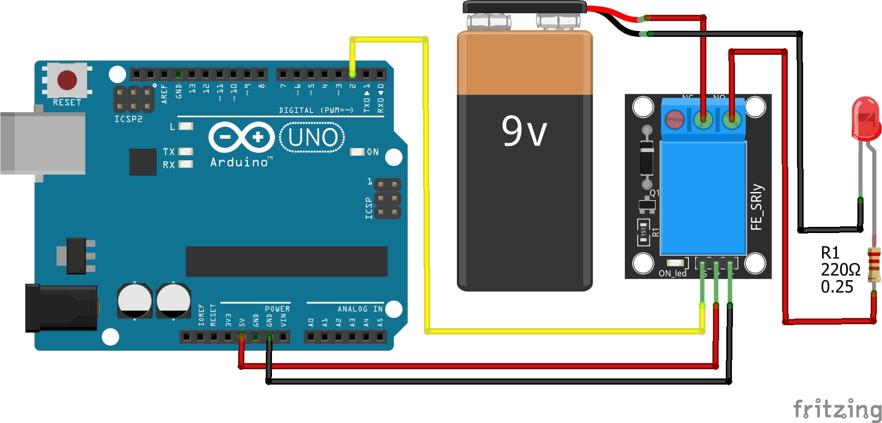
Connecting the 5V Relay Module to an Arduino is fairly simple. The connections are as follows:
- S on the 5V Relay Module to Digital Pin 2 on the Arduino.
- + on the 5V Relay Module to 5V on the Arduino.
- – on the 5V Relay Module to GND on the Arduino.
Connecting the LED and Power Supply (9V battery) to the 5V Relay Module is also very simple. The connections are as follows;
- Common (center pin) on the Relay Module to + on the 9V Battery
- NO (right pin) on the Relay Module to the Anode (longer leg) of the LED with the current limiting resistor in between.
- – on the 9V battery to the Cathode (shorter leg) of the LED
Pin labels may vary.

KY-019 5V Relay Module Fritzing Part is created by arduinomodules.info and published under Creative Commons Attribution-ShareAlike 4.0 International license
Arduino Code Example
const int relay = 2; //

void setup() {
  pinMode(relay, OUTPUT); // set pinmode to output
}

void loop() {
  digitalWrite(relay,HIGH); // turn the relay on high to enable voltage output
  delay(1000); // add one second delay between actions
  digitalWrite(relay,LOW); // turn the relay low to disable voltage output
  delay(1000); // add one second delay between actions
}
Breaking Down the Code
Defining Constants
- A constant integer variable named
relayis declared and initialized with the value 2. This represents the pin number to which the relay module is connected.
Setup Function
pinMode(relay, OUTPUT);sets the mode of the variablerelayto be an output.
Loop Function
digitalWrite(relay,HIGH)turns the relay on by setting the variablerelay(pin 2) to a high voltage level.delay(1000);Adds a delay of 1 seconddigitalWrite(relay,LOW);turns the relay off by setting the variablerelay(pin 2) to a low voltage level.- Another delay of 1 second is added before the loop repeats.
Applications and Usage Scenarios
- Home automation projects for controlling lights, fans, and appliances.
- Industrial automation applications for controlling machinery and equipment.
- Security systems for activating alarms or locking mechanisms.
- Environmental control systems for regulating temperature or humidity.
Safety Considerations
While relay modules offer immense functionality, it’s crucial to prioritize safety, especially when dealing with high-voltage devices. Here are some key safety considerations for all readers:
- Avoid direct contact: Never touch the relay module or any connected high-voltage components while they are powered.
- Isolate high-voltage circuits: Keep high-voltage circuits physically separated from low-voltage components and wiring.
- Use proper insulation: Ensure that all connections and terminals are adequately insulated to prevent electrical shocks or short circuits.
- Follow wiring guidelines: Adhere to recommended wiring practices and ensure proper grounding to minimize the risk of electrical hazards.
- Supervise inexperienced users: If involving young or inexperienced individuals in projects using relay modules, provide close supervision and emphasize the importance of safety precautions.
Conclusion
In this sensors and modules guide, we explained the functionality of the 5V Relay Module, exploring its working principles, and demonstrating how to interface it with an Arduino for practical applications. 5V Relay Modules offer an effective means of controlling high-voltage devices in Arduino projects, enabling a wide range of applications. However, it’s essential to approach their use with caution, particularly concerning safety considerations when dealing with high-voltage circuits. By prioritizing safety and adhering to best practices, you can harness the full potential of relay modules while minimizing the risks associated with working with electricity.
Important: We cannot emphasize this enough, if you are not experienced with high-voltage circuits, you must only experiment with high-voltage circuits when there is a capable adult there to help you.
Discover the endless possibilities for Arduino projects with more of our Sensors and Modules guides.
