
Welcome to the World of Sensors and Modules with Arduino!
Infrared (IR) is a type of electromagnetic radiation with wavelengths longer than those of visible light, but shorter than those of radio waves. It’s invisible to the human eye, but it’s commonly used in various applications. In this sensors and modules guide, we’ll explore the IR Receiver Module and the IR Transmitter Module.
If you’re new to Arduino, why not take a look at our Getting Started with Arduino guides. These guides are designed for beginners to learn the fundamental basics of Arduino programming.
IR Receiver Module
How the IR Receiver Module Works
IR receiver modules are designed to detect infrared signals emitted by IR transmitters. They consist of a photodiode that converts incoming infrared light into electrical signals. These electrical signals are then processed by an amplifier and demodulator to retrieve the original information encoded in the IR signal. The decoded signal can then be utilized by the Arduino to trigger specific actions or responses.
Features and Specifications:
- Operating Voltage: 5V
- Frequency: Typically operates at a frequency range of around 38kHz.
- Size: 24.5mm x 15.5mm
- Compatibility: This sensor is also compatible with other devices like the Raspberry Pi, ESP32, and ESP8266 etc…
IR Transmitter Module
How the IR Transmitter Works
IR transmitter modules emit infrared light pulses at a specific frequency, typically around 38kHz. These pulses carry encoded information that can be decoded by IR receiver modules. The transmitter module consists of an IR LED (Light Emitting Diode) and a driver circuit that modulates the LED to produce the desired infrared signal.
Features and Specifications:
- Operating Voltage: 5V
- Frequency: Typically operates at a frequency range of around 38kHz.
- Size: 37.5mm x 15.5mm
- Compatibility: This sensor is also compatible with other devices like the Raspberry Pi, ESP32, and ESP8266 etc…
Necessary Equipment
- x2 Arduino (e.g., Arduino Uno, Nano etc…)
- IR Receiver Module
- IR Transmitter Module
- Jumper wires
- Breadboard (optional)
For this guide I have opted for the Arduino Nano, they are smaller in size, and I have many of them at hand ready for prototyping with. You can use the Arduino Uno if you wish, the pin connections and diagram will work all the same.
IR Receiver Pin Configuration
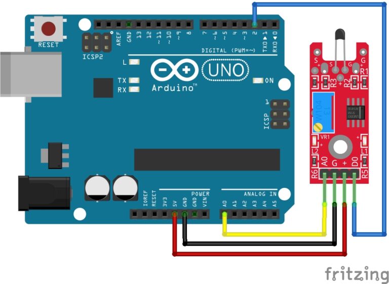
Connecting the IR Receiver Module to an Arduino is fairly simple. The connections are as follows:
- – on the IR Receiver Module to GND on the Arduino.
- + on the IR Receiver Module (middle pin) to 5V on the Arduino.
- S on the IR Receiver Module to Digital Pin 11 on the Arduino.
Pin labels may vary.
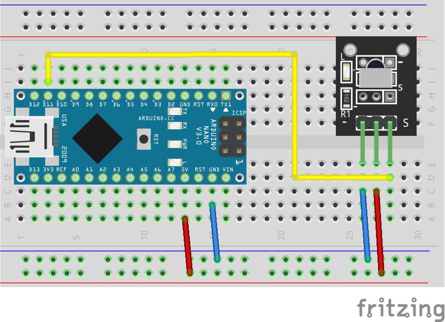
KY-022 Infrared Receiver Module Fritzing Part is created by arduinomodules.info and published under Creative Commons Attribution-ShareAlike 4.0 International license
IR Receiver Arduino Code Example
#include  <IRremote.h> // Include IRremote library

#define IR_RECEIVE_PIN 11 // IR Receiver  Signal pin connected to digital pin 11


void setup() {
  Serial.begin(9600); // Start serial monitor so we can read transmitted  data
  IrReceiver.begin(IR_RECEIVE_PIN, ENABLE_LED_FEEDBACK); // Start the IR Receiver
}

void loop() {
  if (IrReceiver.decode()) { // Check if data is being received
    IrReceiver.printIRResultShort(&Serial); // Start decoding data
    IrReceiver.resume(); // Set ready to receive the next value
  }
}
Breaking Down the Code
Including Libraries
- Include
IRremote.hlibrary, which enables the Arduino to work with infrared signals.
Defining Constants
IR_RECEIVE_PINis the variable which holds the digital pin number to which the IR receiver module is connected. In this case, it’s set to pin 11.
Setup Function
- Serial communication is initiated at a baud rate of 9600. This allows the Arduino to send data to a connected computer.
- The IR receiver is initialized using
IrReceiver.begin(). It specifies the pin number for the receiver (IR_RECEIVE_PIN) and enables LED feedback, which could indicate when the receiver is detecting signals.
Loop Function
- The if Statement checks if the IR receiver is receiving data using
IrReceiver.decode(). - If data is received, it proceeds to decode the data and print a short summary of it to the serial monitor using
IrReceiver.printIRResultShort(&Serial). - Finally, the code resets the IR receiver, ready to receive the next signal using
IrReceiver.resume().
IR Transmitter Pin Configuration
Connecting the IR Transmitter Module to an Arduino is very simple. The connections are as follows:
- – on the IR Transmitter Module to GND on the Arduino.
- S on the IR Transmitter Module to Digital Pin 3 on the Arduino.
Pin labels may vary.
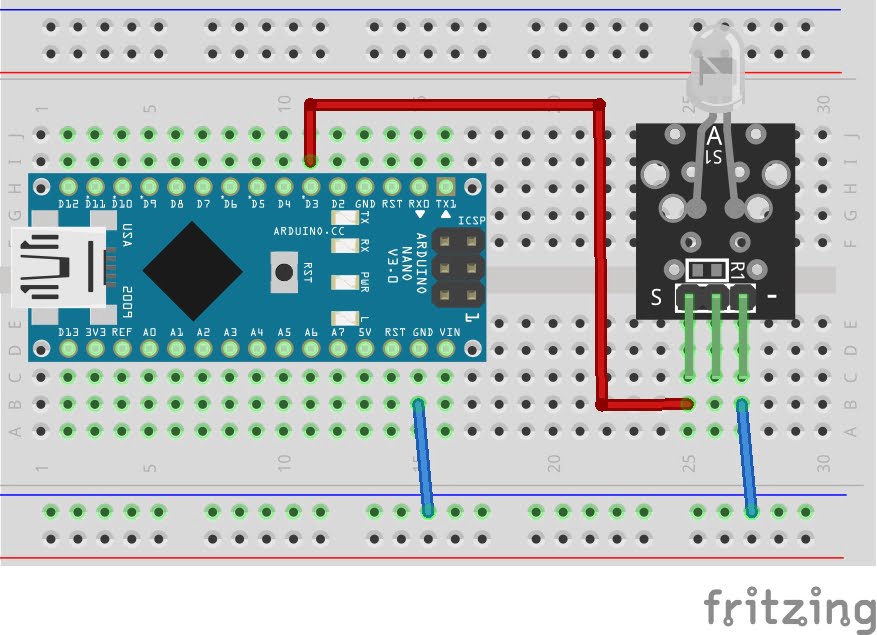
KY-005 Infrared Transmitter Module Fritzing Part is created by arduinomodules.info and published under Creative Commons Attribution-ShareAlike 4.0 International license
IR Transmitter Arduino Code Example
#include  <IRremote.h> // Include IRremote library

const int IR_SEND_PIN = 3; //IR Module Signal pin connected to digital pin 3

IRsend irSender(IR_SEND_PIN); // Initialize the sender

unsigned long data = 0xF30CFF00; // Typical data to transmit

void setup() {
  pinMode(IR_SEND_PIN, OUTPUT); // Set sender mode to output
}

void loop() {
  IrSender.sendNEC(data, 32); // Send data
  delay(1000); // Set a delay to 1 second
}
Breaking Down the Code
Including Libraries
- Include the
IRremote.hlibrary, which facilitates working with infrared signals on Arduino.
Defining Constants
const int IR_SEND_PIN = 3;Defines a constantIR_SEND_PINvariable and assigns to digital pin 3.
Initializing IR Sender
IRsend irSender(IR_SEND_PIN);Initializes the IR sender objectirSender.
Defining Data to Transmit
unsigned long data = 0xF30CFF00;Defines the variabledatawith an unsigned long integer value0xF30CFF00, which represents the data to be transmitted. This value is in hexadecimal format.
Setup Function
pinMode(IR_SEND_PIN, OUTPUT);Configures the pin connected to the IR module as an output pin, indicating that it will be used to send signals.
Loop Function
IrSender.sendNEC(data, 32);Sends the data stored in the variabledatausing the NEC protocol. ThesendNEC()function takes two arguments: the data to send and the number of bits in the data (32 in this case).delay(1000);Introduces a delay of 1000 milliseconds (1 second) before the next transmission. This is done to prevent rapid and continuous transmission.
Applications and Usage Scenarios
IR Remote Extenders
- Combine IR Receiver and IR Transmitter modules to create IR remote extenders, allowing users to control IR devices from extended distances or through obstacles.
Home Automation Integration
- Integrate both modules into a unified home automation system, enabling bidirectional communication between IR-controlled devices and central control units.
Multi-Room Entertainment Control
- Use the IR Receiver and IR Transmitter modules to control audio/video equipment in multiple rooms from a centralized location, enhancing user convenience and flexibility.
Interactive Exhibits and Displays
- Implement both modules in interactive exhibits or displays, allowing users to interact with multimedia content or control exhibit features using IR remote controllers.
By leveraging the capabilities of both IR receiver and transmitter modules, developers can create a wide range of applications, from simple remote-control systems to sophisticated home automation setups and interactive multimedia experiences. The seamless integration of these modules enables versatile and intuitive control solutions tailored to specific needs and requirements.
Conclusion
In this sensors and modules guide, we explained the functionality of the IR Receiver and IR Transmitter Modules, exploring their working principles, and demonstrating how to interface them with Arduino for practical applications. The IR Receiver Module and IR Transmitter Module serve as indispensable tools for Arduino enthusiasts and electronic hobbyists alike. Their ability to harness the power of infrared light enables a myriad of applications, ranging from home automation to robotics. By understanding their features, working principles, and applications, we can unlock the full potential of these versatile modules in our own Arduino projects.
Discover the endless possibilities for Arduino projects with more of our Sensors and Modules guides.
I learned something new today.
This is very well-done.
Thanks for the comprehensive overview. Very helpful!