

What are Pull-up and Pull-down Resistors?
In Arduino programming, INPUT_PULLUP and INPUT_PULLDOWN are two options you can use when configuring digital pins as input pins. These options help you enable built-in pull-up or pull-down resistors on the pins to ensure a stable logic level when the pins are not actively being driven high or low by external components. There is also another way to create pull-up and pull-down resistors.
INPUT_PULLUP:
- When you configure a digital pin as
INPUT_PULLUP, you are enabling the internal pull-up resistor for that pin. A pull-up resistor is connected between the pin and the voltage supply (usually 5V on most Arduino boards). - The purpose of a pull-up resistor is to ensure that the pin reads a logical HIGH (1) when it’s not actively being driven LOW (0) by an external component. It effectively “pulls up” the voltage level to HIGH when the pin is left unconnected.
- This is useful, for example, when you have a button or switch connected between the pin and ground. When the button is not pressed, the pin will read HIGH because of the pull-up resistor. When you press the button, it will connect the pin to ground, making it read LOW.
- Example usage:
pinMode(buttonPin, INPUT_PULLUP);
INPUT_PULLDOWN:
- On some Arduino boards (like the Arduino Due and Arduino Zero), you have the option to configure a pin as
INPUT_PULLDOWN. This enables the internal pull-down resistor for that pin. - A pull-down resistor is connected between the pin and ground. It serves the opposite purpose of a pull-up resistor by ensuring that the pin reads a logical LOW when it’s not actively being driven HIGH by an external component.
- This can be useful in situations where you want the default state of the pin to be LOW and have it go HIGH when an external component drives it.
- Example usage (on supported boards):
pinMode(pin, INPUT_PULLDOWN);
Basic Example:
Here’s a simple code example that demonstrates the use of INPUT_PULLUP with a button:
const int buttonPin = 2; // The pin where your button is connected

void setup() {
  pinMode(buttonPin, INPUT_PULLUP);
  Serial.begin(9600);
}

void loop() {
  int buttonState = digitalRead(buttonPin);
  if (buttonState == LOW) {
    Serial.println("Button pressed!");
  }
}
In this example, the internal pull-up resistor is used to keep the button pin HIGH when the button is not pressed. When the button is pressed, the pin is connected to ground, causing digitalRead() to return LOW, and the message is printed to the serial monitor.
Let's Build!
Example 1:
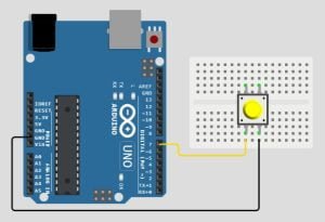
This example demonstrates how to make use on the Arduino’s internal pullup resistor.
The Code:
Copy and paste the code below to a new Arduino sketch:
int PIN = 7;

void setup() {
  Serial.begin(9600);
  pinMode(PIN, INPUT_PULLUP);
}

void loop() {
  Serial.println(digitalRead(PIN));
  delay(500);
}
The Circuit:
Assemble your components in the same way as the image below, if you want to see the results for yourself!
Upload the Code:
Arduino digital pins read and write binary data, HIGH or LOW, 1 or 0. We set a digital pin to either an OUTPUT or an INPUT. The Arduino has a third option, INPUT_PULLUP. When INPUT_PULLUP is defined in the pinMode() an internal resistor is pulled up to 5v keeping the pin at a constant HIGH so if you took a reading of that pin with digitalRead() it would read 1.
Once the code is uploaded to the Arduino board, open the serial monitor. As you can see the pin has been pulled HIGH and reads 1. Press the push button and the pin will go low and will read 0. This is great for executing a command in our code by simply adding:
if(PIN==0){
  Do something;
}
Example 2:
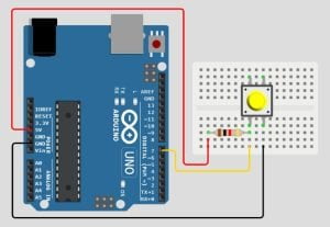
We do not need to use the internal pullup resistor to do this, we can create the exact same action by using a 10k ohm resistor and one more jumper wire.
The Code:
Copy and paste the code below to a new sketch:
int PIN = 7;
void setup() {
  Serial.begin(9600);
  pinMode(PIN, INPUT);
}
void loop() {
  Serial.println(digitalRead(PIN));
  delay(500);
}
The Circuit:
To follow along, assemble your components the same as below. Don’t forget to add the 10k ohm resistor.
Upload the Code:
Now upload the code to your Arduino board. Once uploaded open the serial monitor and you will see the same as before, the pin has been pulled HIGH and our digitalRead() reads a 1, press the push button and it’s pulled down to ground and reads a 0.
Example 3
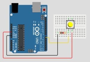
We can also use pulldown, but the Arduino doesn’t have an internal resistor that pulls down, so just like the last example we can use a 10k ohm resistor, but this time instead of connecting it to 5v we swap the 5v and GND wires around.
The Circuit:
Swap the 5v and the GND wires around and then open the serial monitor. Just like in the image below. Now you will see the pin is pulled LOW and reads 0, press the push button and it will be pulled HIGH, and read 1.
Conclusion
In Arduino programming, INPUT_PULLUP and INPUT_PULLDOWN are options used to configure digital pins as inputs with built-in resistors. INPUT_PULLUP activates an internal pull-up resistor, maintaining a HIGH state when not actively driven LOW. INPUT_PULLDOWN (available on some boards) activates an internal pull-down resistor, keeping the pin at a LOW state when not actively driven HIGH. These options simplify input handling in Arduino projects, particularly for buttons and switches.
Recommendations:
If you don’t already own any Arduino hardware, we highly recommend purchasing the Elegoo Super Starter Kit. This kit has everything you need to start programming with Arduino.
You can find out more about this kit here: Elegoo Super Starter Kit


Very nice post. I just stumbled upon your blog and wanted to say that I’ve really enjoyed browsing your blog posts. In any case I’ll be subscribing to your feed and I hope you write again soon!