

Introduction to Arduino
Moreover, Arduino’s core components, hardware and software, work seamlessly together. Similarly, the Arduino IDE simplifies writing and uploading code in a beginner-oriented version of C/C++. Firstly, we’ll cover a little about the Arduino board and pins. Then, we can move onto the installation of the IDE. Finally, we can begin writing your first program.
Why is Arduino Special?
At the outset, Arduino’s accessibility draws many users. It simplifies electronics and coding. Specifically, its hardware is straightforward. The Arduino IDE is user-friendly too. This eases the learning curve. Also, Arduino is open-source. It shares hardware and software details freely. This builds a collaborative community.
In addition, Arduino’s versatility fuels creative projects. It supports interactive art and robotics. Home automation is possible too. Finally, Arduino offers extensive libraries. These provide pre-written code. They simplify complex tasks. This speeds up project development.
Introduction to the Arduino Pins
As you embark on your Arduino journey, understanding the various pin types on your board is essential for bringing your projects to life. In turn, mastering these pins empowers you to connect components like LEDs, sensors, or motors with confidence. Specifically, Arduino boards feature digital pins for basic on/off signals, analog pins for reading variable inputs like sensors, and PWM pins for controlling devices such as motors or dimmable LEDs. Moreover, each pin type serves unique roles in your circuits, making them critical for project success. Ultimately, by exploring these pin types in this lesson, you’ll gain the knowledge to select the right pins for your creative endeavors.
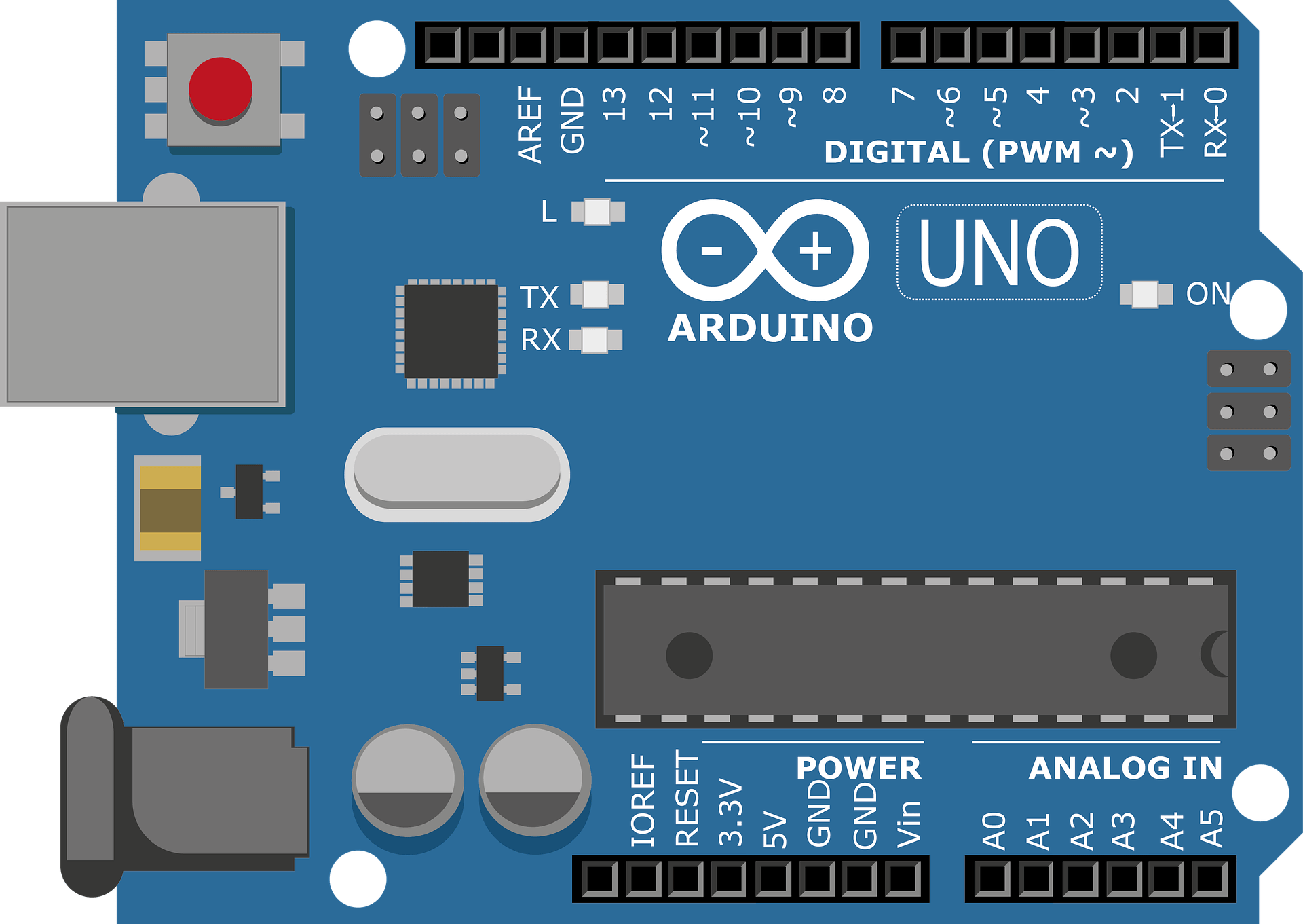
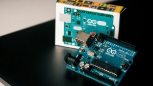
Initially, the Arduino Uno has 14 digital pins. These handle input or output signals. Six pins support PWM for dimming LEDs or controlling motors. Also, it offers six analog pins. These read sensor signals. The Uno includes a 16 MHz resonator and USB port. It has a power jack and reset button too. Notably, an ICSP header allows advanced connections. All essentials run the microcontroller. Easily power it with a USB cable. A 9V battery works for standalone projects.
Above all, the Uno is beginner-friendly. Errors are low-cost. Just replace the chip if issues arise.
Types of Arduino Pins
Now, let’s explore the Arduino’s pin types. These pins bring projects to life. They connect components like LEDs or sensors. Soon, you’ll master their project roles.
Digital Pins
To start, digital pins manage on/off signals. These signals are HIGH or LOW. HIGH means 5 volts. LOW means 0 volts. For instance, HIGH turns LEDs on and LOW turns them off. Now, the Uno has 14 digital pins, they are labeled 0 to 13. Plus, six pins support PWM. These are pins 3, 5, 6, 9, 10, 11. PWM for example, controls an LED brightness. Thus, use pins for LEDs. Additionally, digital sensors work too.
Analog Pins
To begin, analog pins sense varying voltages. They read from 0 to 5 volts. These pins turn voltages into numbers. Numbers range from 0 to 1023. For example, they can work with sensors. Now, some sensors can measure light or temperature. So, the numbers range helps take accurate readings.
Next, the Uno has six analog pins. They are labeled A0 to A5. Also, these pins suit sensors. Potentiometers or temperature sensors work well. In fact, a potentiometer adjusts LED brightness. It changes the voltage read. Thus, analog pins power variable input projects.
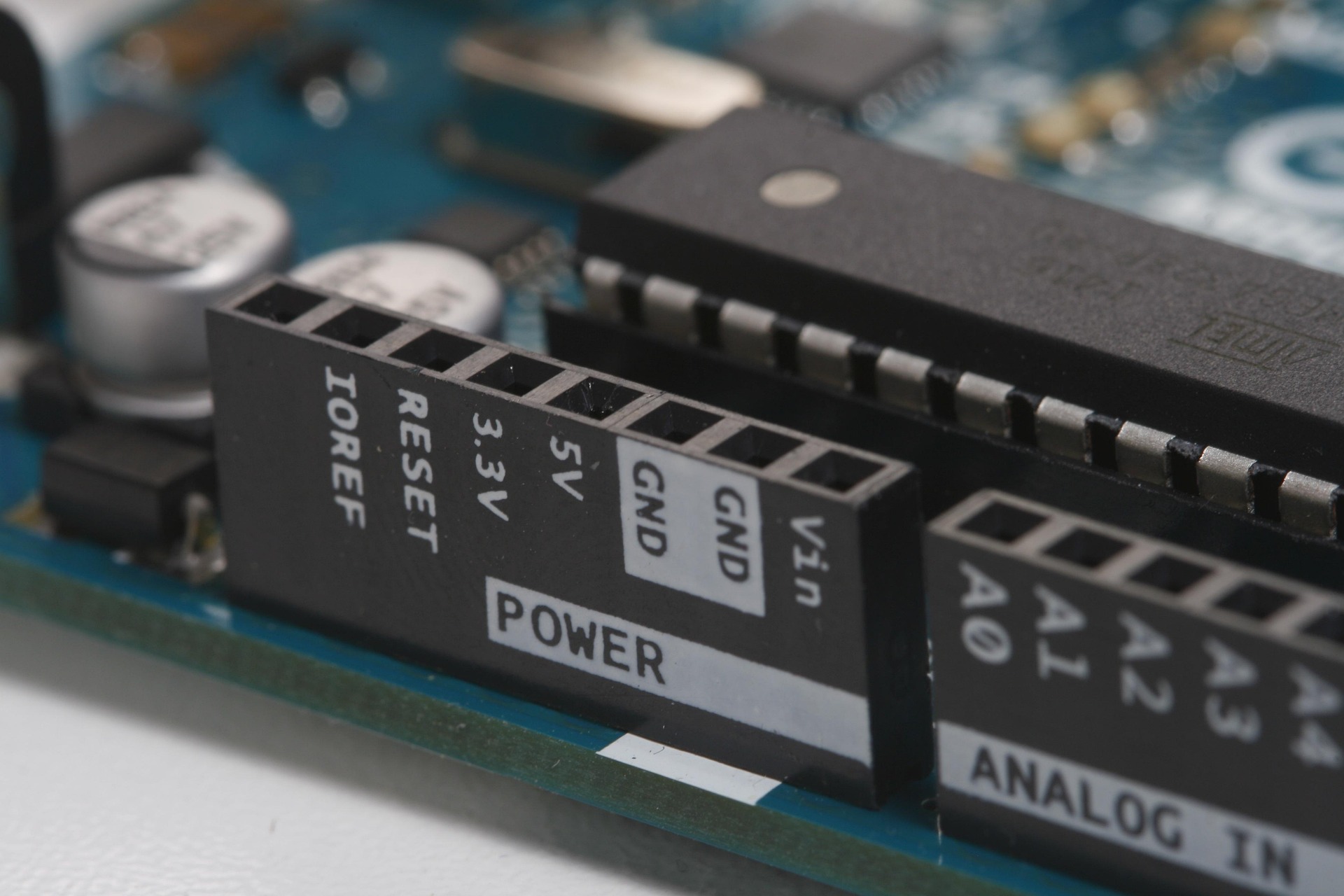
Power Pins
To start, power pins supply or receive power for the Arduino board and its components. For example, you can use the 5V pin and GND to power an LED circuit. The 5V pin outputs 5V to power components. Also, the 3.3V pin provides 3.3V for specific devices, such as low-power sensors. Additionally, GND pins complete circuits, and the Uno has multiple GND pins. Finally, the Vin pin serves as a power input or output pin.
Special Arduino Pins
First, special Arduino pins have unique functions beyond standard input or output. For example, the IOREF pin outputs the board’s operating voltage. This helps shields match the correct logic level. Also, the AREF pin sets the reference voltage, 0 to 5V, for precise sensor readings. Next, the ICSP header allows programming the microcontroller or connecting shields.
Additionally, the Reset pin restarts the board when pulled LOW. For instance, TX and RX pins, on pins 0 and 1, handle serial communication. Similarly, external interrupt pins, on pins 2 and 3, trigger special actions when signals change.
Lastly, I2C and SPI pins link devices. I2C uses A4 and A5. SPI uses pins 10 to 13. These support sensors, modules or displays.
Tips: Now, some pins have multiple functions. For example, analog pins A0–A5 can act as digital I/O if not used for analog input. Next, always check the Arduino pinout diagram for your specific board to confirm pin roles, as models vary slightly. Also, ensure components match your board’s voltage, like 5V for the Uno, to avoid damage. Additionally, here’s how to recall I2C pins with ease. SCL means Serial Clock. It has five letters. So, SCL uses pin A5. SDA means Serial Data. It has four letters. Thus, SDA uses pin A4.
Installing the Integrated Development Environment (IDE)
To begin, download the IDE here. Once downloaded just double-click the file to start the installation process. Also, we recommend you just accept the default setting throughout the process.
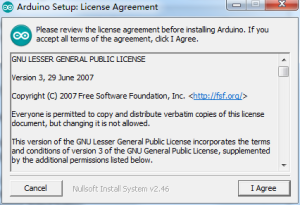
First, agree to the terms and conditions.
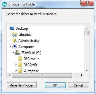
Next, choose destination for the Arduino installation.
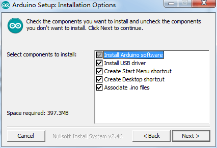
Now, leave default installation options.
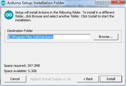
Next, select install.
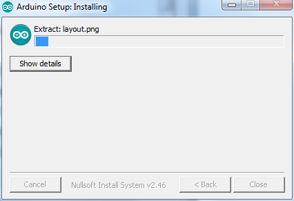
Finally, wait for the install process to complete.
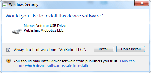
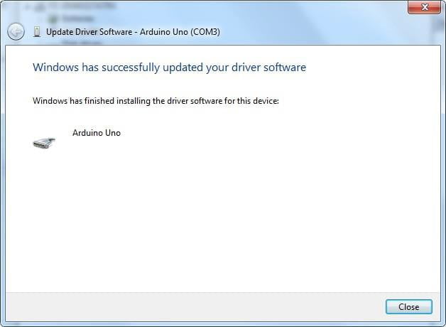
Windows security should prompt you to allow the driver installation. Again, click on install.
Next, connect your board to your computer using the supplied USB cable.
What if your Arduino Board is not Recognized?
To open device manager use either of these options:
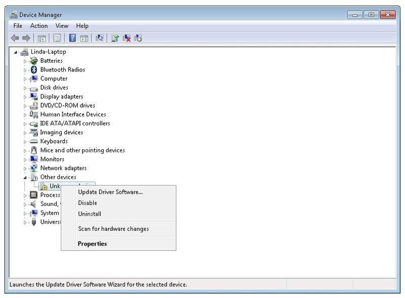
Now, right click on the device being flagged and select Update Driver Software.
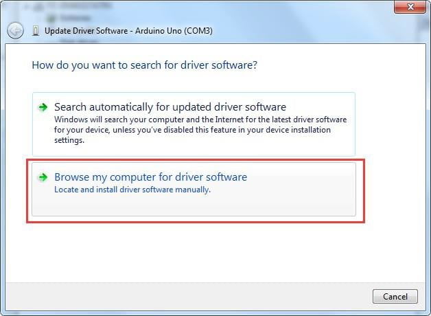
Next, select Browse my computer for driver software.
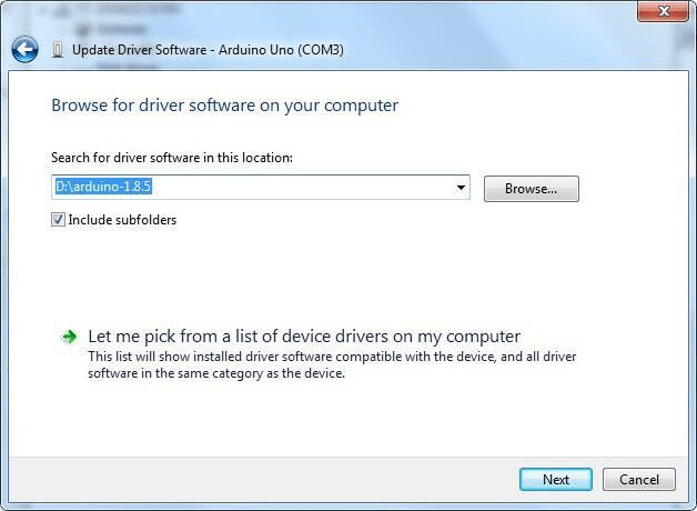
Finally, browse for the location where Arduino was installed to.
However, if the problem persists, please run through the steps again. Now, select automatic driver search instead.
This will scan your computer and the internet to find the required drivers.
First Look at the Arduino IDE
Now, once the IDE is installed and your computer recognizes the board, you’re ready to start coding.
First, open your Arduino IDE program.
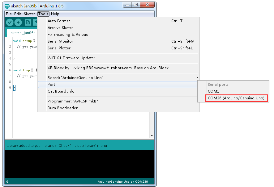
Next, in the IDE select Tools scroll down to Board, make sure its set to “Arduino/Genuino Uno”
Finally, just below you should see Port, select the COM port your board is connected to.
Verify your Code
First, the image below shows the Verify icon, a tick in the Arduino IDE. For example, clicking this icon checks your code for errors before uploading it to the board. Also, it ensures your code is correct without running it on the Arduino. Then, fix any errors shown in the IDE’s error log to make your code work properly.

How to Upload your Code
First, the image below highlights the Upload icon, a right-facing arrow in the Arduino IDE. For example, clicking this icon compiles your code and sends it to the UNO board. Also, ensure your board and port are selected in the Tools menu before uploading. Then, wait for the IDE to confirm the upload is complete.

The Serial Monitor
First, the image below highlights the Serial Monitor icon, a magnifying glass on the top right of the Arduino IDE. For example, this tool shows data sent between the Arduino and your computer via the USB cable. Also, we use print statements in the Serial Monitor to debug our code. For instance, these statements can pinpoint exactly where the code fails. Additionally, throughout these lessons, you’ll use print statements to display various types of data.
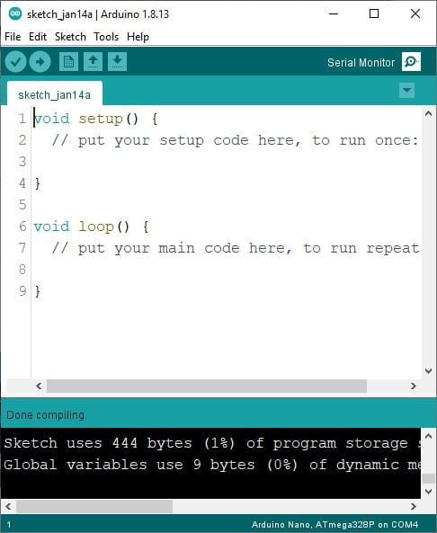
First, the image above shows two main sections of Arduino code. For example, the void setup() section runs its code once when the board starts. Also, the void loop() section repeatedly runs its code in a continuous loop. For instance, use setup() to initialize settings, like pin modes, and loop() to control actions, like blinking an LED.
Writing Your First Arduino Program: Hello, World!
First, since you’ve installed the Arduino IDE and set up your board, it’s time to write your first program. For example, the classic “Hello, World!” program prints a message to the Serial Monitor. Also, this simple step lets you see your Arduino in action. For instance, it confirms your setup works correctly.
Step 1: Write the Code
Now, copy the following code into a new sketch:
/*
This is a multi-line comment.
It can span multiple lines and is useful for detailed explanations or notes.
This program prints "Hello, World!" every second to the Serial Monitor.
*/
void setup() {
  // Start the Serial Monitor at 9600 baud <- This is a single line comment
  Serial.begin(9600);
}

void loop() {
  Serial.println("Hello, World!"); // <- This is a print statement it prints the message to the Serial Monitor
  delay(1000); // Wait 1 second before printing again
}
Step 2: Upload the Code
First, click the Upload button in the Arduino IDE to send your code to the board. For example, this compiles and transfers the “Hello, World!” program to your UNO.
Step 3: View the Output
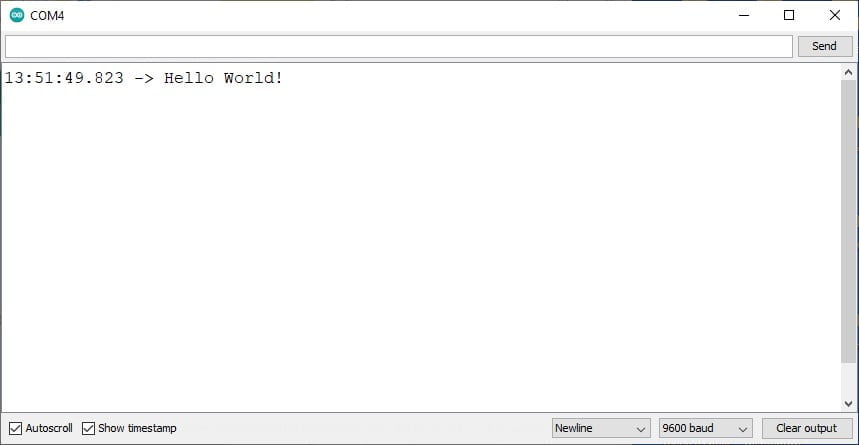
Next, open the Serial Monitor by clicking the magnifying glass icon. Then, set the baud rate to 9600 in the Serial Monitor’s dropdown. Also, check that “Hello, World!” prints every second. For instance, if nothing appears, ensure your board is connected properly.
What’s Happening?
Firstly, Serial.begin(9600) starts communication with the Serial Monitor. Next, Serial.println(“Hello, World!”) sends the message to display. Additionally, delay(1000) pauses for 1 second, looping the message continuously. Finally, the setup() function runs once to initialize, while loop() runs repeatedly.
Understanding Comments and Print Statements
Single-Line Comments: These begin with // and are used for short, one-line explanations. For example, // Print the message to the Serial Monitor clarifies what the Serial.println() line does. Single-line comments help you and others understand the code without affecting how it runs. They’re perfect for quick notes next to specific lines.
Multi-Line Comments: These start with /* and end with */, allowing you to write comments across multiple lines. In the code above, the multi-line comment at the top explains the program’s overall purpose. Consequently, multi-line comments are ideal for detailed descriptions or notes about your sketch’s functionality.
Print Statements: The line Serial.println(“Hello, World!”); is a print statement that sends the text “Hello, World!” to the Serial Monitor, followed by a new line. Additionally, the Serial.begin(9600); line in setup() initializes serial communication at 9600 baud (a speed setting for data transfer). Print statements are crucial for beginners because they let you see your Arduino’s output or debug issues. For instance, you can open the Serial Monitor in the Arduino IDE (set to 9600 baud) to view the repeated “Hello, World!” messages.
Try modifying the text in Serial.println() (e.g., “My Arduino Works!”) or changing the delay to experiment with the timing!Conclusion
Finally, if you have any questions or want to share your projects? Connect with us on X/Twitter for more tips and inspiration!
Ready for more? click Next to continue learning.
