

What are Arduino Components?
“Arduino components” typically refers to electronic components and modules that are commonly used in conjunction with Arduino microcontrollers to build various electronic projects and prototypes. These components are essential building blocks for creating a wide range of projects, from simple LED blinkers to complex robotics and IoT devices.
Here are some common Arduino components:
LEDs (Light Emitting Diodes):
- Used for visual indicators and lighting effects in projects.
Resistors:
- Used to limit current, control voltage, and protect components.
Capacitors:
- Store and release electrical energy and can be used for filtering and timing.
Transistors:
- Used for switching and amplifying signals in digital and analog circuits.
Diodes:
- Used to control the direction of current flow in a circuit.
Sensors:
- Various sensors, such as temperature sensors, humidity sensors, motion sensors, and light sensors, are used to measure and respond to environmental conditions.
Motors:
- DC motors, servo motors, and stepper motors are used for controlling motion in projects.
Displays:
- LCD displays, OLED displays, and 7-segment displays are used for visualizing data and information.
Relays:
- Used to control high-power devices like motors, lights, and appliances.
Breadboards:
- Prototyping boards for creating and testing circuits without soldering.
Buttons and Switches:
- Used for user input and control in projects.
Potentiometers:
- Variable resistors used for analog input or to control the intensity of components like LEDs.
Buzzers and Speakers:
- Used for audio output and generating tones and sounds.
Ultrasonic Sensors:
- Used for measuring distance and proximity in robotics and automation projects.
IR (Infrared) Modules:
- Used for remote control and communication.
Bluetooth and Wi-Fi Modules:
- Enable wireless communication and connectivity with smartphones and other devices.
Motor Drivers:
- Control the speed and direction of motors in robotic applications.
RTC (Real-Time Clock) Modules:
- Provide accurate time and date information to Arduino projects.
Relay Modules:
- Expands the capability of relays for controlling various high-power devices.
Voltage Regulators:
- Used to provide a stable voltage supply to the Arduino and other components.
These components, when combined with an Arduino board and programmed using the Arduino IDE, allow makers and electronics enthusiasts to create a wide variety of projects, from simple to highly complex. The versatility and accessibility of these components make Arduino a popular choice for hands-on learning and prototyping in the world of electronics and robotics.
Recommendations:
If you don’t already own any Arduino hardware, we highly recommend purchasing the Elegoo Super Starter Kit. This kit has everything you need to start programming with Arduino.
You can find out more about this kit here: Elegoo Super Starter Kit
Here’s a brief explanation of the Arduino components we will be using:
Resistors:
Resistors are passive electronic components that limit the flow of electrical current in a circuit. They are commonly used in Arduino projects to control voltage levels, limit current, and protect other components.
LEDs (Light Emitting Diodes):
LEDs are semiconductor devices that emit light when current flows through them. They are often used in Arduino projects to indicate status, create visual effects, or provide feedback.
RGB LEDs (Red-Green-Blue LEDs):
RGB LEDs are special LEDs that can emit light in multiple colors by varying the intensity of the red, green, and blue components. They are used for colorful lighting effects in projects.
Tactile Switches:
Tactile switches, also known as push-button switches, are used to create momentary connections in a circuit. They are often used for user input in Arduino projects, such as triggering actions or changing modes.
DHT-11 (Temperature and Humidity Sensor):
The DHT-11 is a sensor that measures temperature and humidity in the environment. It’s commonly used in weather monitoring, climate control, and environmental sensing projects.
Light Dependent Resistor (LDR):
An LDR is a variable resistor whose resistance changes with the amount of light it receives. It’s used in Arduino projects to detect light levels and create light-sensitive applications.
DC Motors:
DC (Direct Current) motors are used for motion control in Arduino projects. They convert electrical energy into mechanical motion and are widely used in robotics, vehicles, and automation projects.
Servo Motors:
Servo motors are precise motors that can rotate to specific angles. They are commonly used for precise positioning and control tasks in Arduino projects, such as controlling robot arms or steering mechanisms.
IR (Infrared) Module:
An IR module is used to send and receive infrared signals. It’s often used in Arduino projects for remote control applications, communication with infrared devices, and object detection.
Breadboard:
The breadboard is a tool for prototyping electronic circuits without soldering. It consists of a grid of holes where components and wires can be inserted, making it easy to experiment with circuit designs and make changes quickly.
These components are fundamental in the world of Arduino and electronics, and they can be used in various combinations to create a wide range of innovative and creative projects.
Understanding the Breadboard
A breadboard is a fundamental tool used in electronics for prototyping and building temporary circuits without the need for soldering. It consists of a grid of holes, typically arranged in rows and columns, and is mounted on a plastic or metal base. Breadboards are widely used by hobbyists, engineers, and students to quickly test and experiment with electronic circuits. Here’s a brief explanation of how breadboards work:
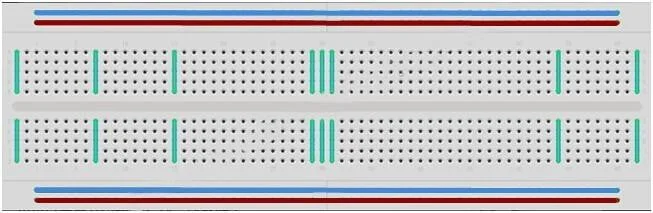
Structure of a Breadboard:
Rows: Breadboards have rows of holes, typically labeled with numbers or letters, running horizontally. These rows are often used for connecting power and ground (positive and negative) rails or for making horizontal connections between components.
Columns: The columns of holes are typically arranged in groups of five, and each group is electrically connected internally. Components are inserted into these columns to create connections.
Power Rails: Most breadboards have two long rows on the edges, often marked as “+ (red)” and “- (blue)” or something similar. These are the power rails. The plus rail is typically used for connecting the positive side of a power supply (e.g., 5V), and the minus rail is used for connecting the ground (0V or GND).
How Breadboards Work:
Inserting Components: To build a circuit on a breadboard, you insert components such as resistors, LEDs, and wires into the holes. Components connect to each other by inserting their leads or wires into the appropriate holes in the same row or column.
Internal Connections: Inside the breadboard, the holes in each row are electrically connected. This means that if you place a component’s lead or wire in one hole in a row, it is electrically connected to all the other holes in that same row. The same goes for columns, where the holes are connected vertically.
No Soldering: The key advantage of breadboards is that they allow you to create and modify circuits quickly without soldering. This makes them ideal for prototyping and experimenting.
Creating Our First Circuit
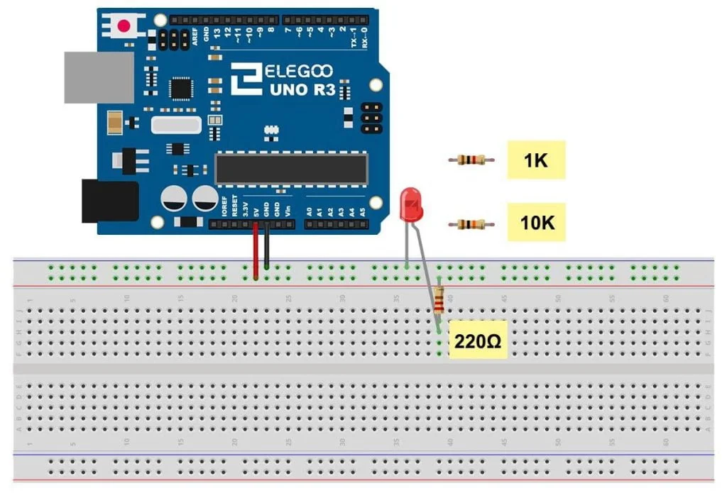
Below is an image of a basic LED Circuit.
- Insert a 220 Ohm resistor into the red horizontal row (5v) on the breadboard and the other leg in the nearest available vertical row in the center section of the breadboard.
- Insert the short leg of the LED into the blue horizontal row (GND) on the breadboard and insert the long leg into the center section of the breadboard in the same vertical row we inserted the resistor to.
- Use a jumper wire and connect 5v on the Arduino to any hole in the red horizontal row (Live) on the breadboard.
- Now using another jumper wire connect GND on the Arduino to the blue horizontal row (GND) on the breadboard.
- Now plug the USB cable into your Arduino, and then plug the other end into your computer.
- We should now have the LED emitting light.
If we hadn’t used the resistor, we could have damaged the LED permanently.
Conclusion
By understanding the structure of a breadboard and the direction of component polarity, you can effectively build and test electronic circuits for your projects.
All the components mentioned here are going to be our main focus while learning this “Getting started with Arduino” series.
Happy Tinkering!


