
Building our First Radio Controlled Arduino Project
The NRF24L01 RF Module is a low-cost, high-performance 2.4GHz transceiver module widely used for wireless communication in Arduino projects. It operates on the 2.4GHz ISM band and provides reliable communication over a considerable distance, making it ideal for remote control applications. In this guide, we’ll walk you through the process of building a simple wireless communication system between two Arduino boards. By the end of this tutorial, you’ll be able to remotely control a servo motor and a DC motor connected to one Arduino board from another Arduino board with a joystick.
If you have stumble across this post and have not yet used the NRF24L01 RF module then why don’t you take a look at this beginner guide here: NRF24L01 RF Module for Beginners. We also have another guide for building your first radio with Arduino, you can find it here: Buidling your first Radio with Arduino.
How It Works
In this project, we’ll set up one Arduino board as the transmitter and another Arduino board as the receiver. The transmitter Arduino will read input from a joystick module (or any other analog input device) and transmit this data wirelessly using the NRF24L01 module. The receiver Arduino will receive this data and use it to control a servo motor and a DC motor connected to it.
Getting Started
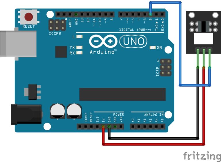
Before we dive into the code and wiring, let’s make sure you have your hardware set up correctly. Carefully follow the wiring diagrams provided in this guide to connect your Arduino boards with the NRF24L01 modules, and other components correctly.
Building the RF Control Transmitter
Before we dive into the code, let’s get the necessary components ready for building the transmitter, and then I will show you how to connect these components to your Arduino board.
Necessary Equipment:
- Arduino board (e.g. Uno, Nano etc…)
- NRF24L01 RF module
- Joystick module
- Breadboard
- Jumper wires
All of these components can be found in the Elegoo Super Starter kit except for the NRF24L01 module, this needs to be purchased separately.
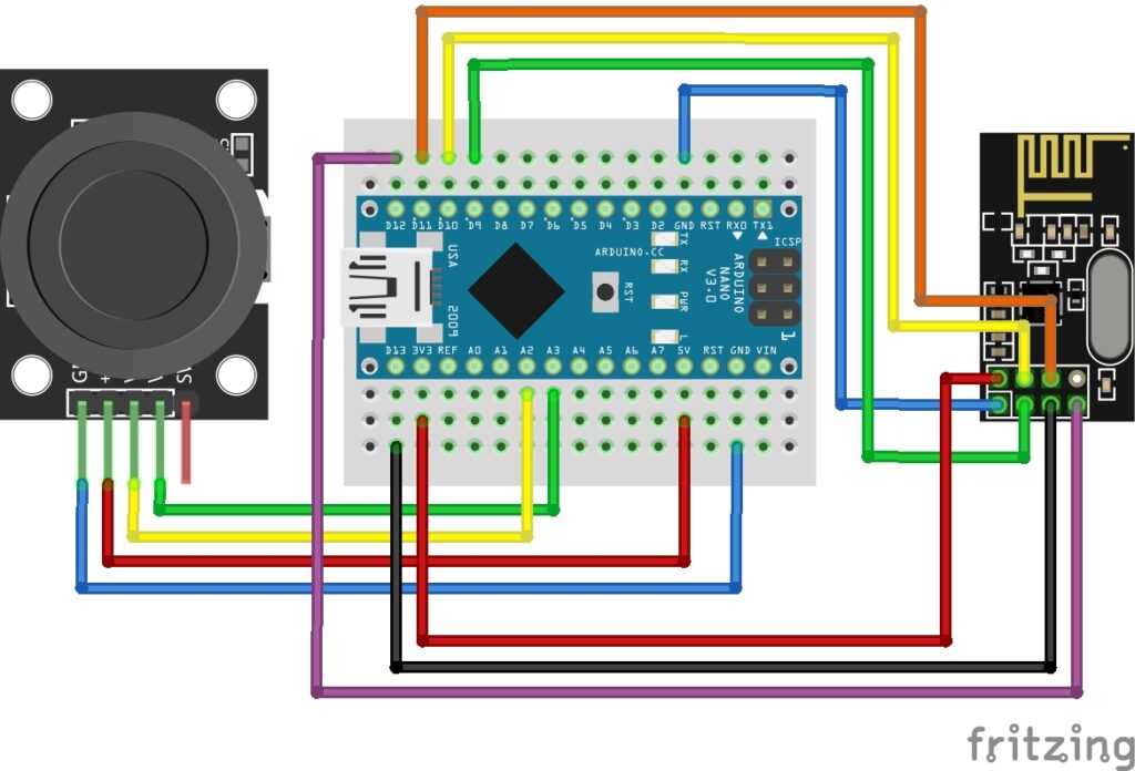
Pin Configuration:
- NRF24L01:
- VCC on the NRF24L01 module to 3.3V on the Arduino (unless you are using the base board then you can connect it to 5V).
- GND on the NRF24L01 module to GND on the Arduino.
- CSN (Chip Select) on the NRF24L01 module to Digital pin 10 on the Arduino.
- CE (Chip Enabled) on the NRF24L01 module to Digital pin 9 on the Arduino.
- SCK (Serial Clock) on the NRF24L01 module to Digital pin 13 on the Arduino.
- MOSI (Master Out Slave in) on the NRF24L01 module to Digital pin 11 on the Arduino.
- MISO (Master in Slave Out) on the NRF24L01 module to Digital pin 12 on the Arduino.
- IRQ: This pin is optional and may be left unconnected as we won’t be using it for this guide. It is used for interrupt handling.
- Joystick:
- GND on the Joystick to GND on the Arduino.
- 5V on the Joystick to 5V on the Arduino.
- VRX on the Joystick to Analog pin A2 on the Arduino.
- VRY on the Joystick to Analog pin A3 on the Arduino.
Pin labels may vary.
Arduino Transmitter Code Example
Here is the code I used to control the transmitter. Once you are ready, upload the code to the Transmitter Arduino.
#include <SPI.h>
#include <RF24.h>

#define CE_PIN 9
#define CSN_PIN 10

RF24 radio(CE_PIN, CSN_PIN);

int JoyAxisX = A2; // Forward / Reverse
int JoyAxisY = A3; // Left / Right
int xVal;
int yVal;

struct JoystickData {
  int x;
  int y;
};

JoystickData joystickData;

void setup() {
  Serial.begin(9600);
  radio.begin();
  radio.setPALevel(RF24_PA_LOW); // Set power level to low
  radio.openWritingPipe(0xF0F0F0F0E1LL); // Set the transmitting address
}

void loop() {
  // Take Joystick Readings
  xVal = analogRead(JoyAxisX);
  yVal = analogRead(JoyAxisY);

  // Populate JoystickData struct
  joystickData.x = xVal;
  joystickData.y = yVal;

  // Send Joystick Data
  radio.write(&joystickData, sizeof(joystickData));

  Serial.println("Joystick Data Sent!");
  delay(500);
}
Breaking Down the Code
Let’s break down the transmitter code step by step:
Step 1: Include Libraries
These lines include the necessary libraries for SPI communication and the NRF24L01 module.
#include <SPI.h>
#include <RF24.h>
Step 2: Define Pins:
These lines define the pins used for the CE (Chip Enable) and CSN (Chip Select Not) of the NRF24L01 module.
#define CE_PIN 9
#define CSN_PIN 10
Step 3: Create RF24 Object
This line creates an instance of the RF24 class with the specified CE and CSN pins.
RF24 radio(CE_PIN, CSN_PIN);
Step 4: Define Joystick Pins and Variables
These lines define the analog pins used for reading joystick data (x and y axes) and variables to store the joystick readings.
int JoyAxisX = A2; // Forward / Reverse
int JoyAxisY = A3; // Left / Right
int xVal;
int yVal;
Step 5: Define JoystickData Structure
This defines a structure named JoystickData containing two integer variables for x and y joystick values.
struct JoystickData {
int x;
int y;
};
Step 6: Declare JoystickData Variable
This declares a variable named joystickData of type JoystickData to store the current joystick readings.
JoystickData joystickData;
Step 7: Setup Function
void setup() {
  Serial.begin(9600);
  radio.begin();
  radio.setPALevel(RF24_PA_LOW); // Set power level to low
  radio.openWritingPipe(0xF0F0F0F0E1LL); // Set the transmitting address
}
In the setup function:
- Serial communication is initialized at a baud rate of 9600.
- The NRF24 module is initialized.
- The power level of the module is set to low.
- The transmitting address for the radio is set.
Step 8: Loop Function
void loop() {
  // Take Joystick Readings
  xVal = analogRead(JoyAxisX);
  yVal = analogRead(JoyAxisY);

  // Populate JoystickData struct
  joystickData.x = xVal;
  joystickData.y = yVal;

  // Send Joystick Data
  radio.write(&joystickData, sizeof(joystickData));

  Serial.println("Joystick Data Sent!");
  delay(500);
}
In the loop function:
- Joystick readings are obtained by reading analog values from the x and y axis pins.
- The
JoystickDatastructure is populated with the x and y values. - The joystick data is sent over the NRF24 module using the
radio.writefunction. - A message indicating that joystick data has been sent is printed to the Serial monitor.
- A delay of 500 milliseconds is added to control the transmission rate.
Building the RF Control Receiver
Now that we have the transmitter built, we can move onto the receiver side. Let’s take a look at what you need and how to build the RF control receiver.
Necessary Equipment:
- Arduino board (e.g. Uno, Nano etc…)
- NRF24L01 RF module
- L9110 Motor controller
- Servo motor
- DC motor
- Breadboard
- Breadboard power supply module
- Jumper wires
- 9V battery
- 9V battery barrel jack connector
Again, all of these components can be found in the Elegoo Super Starter kit except for the NRF24L01 or L9110 Motor driver modules, these need to be purchased separately.
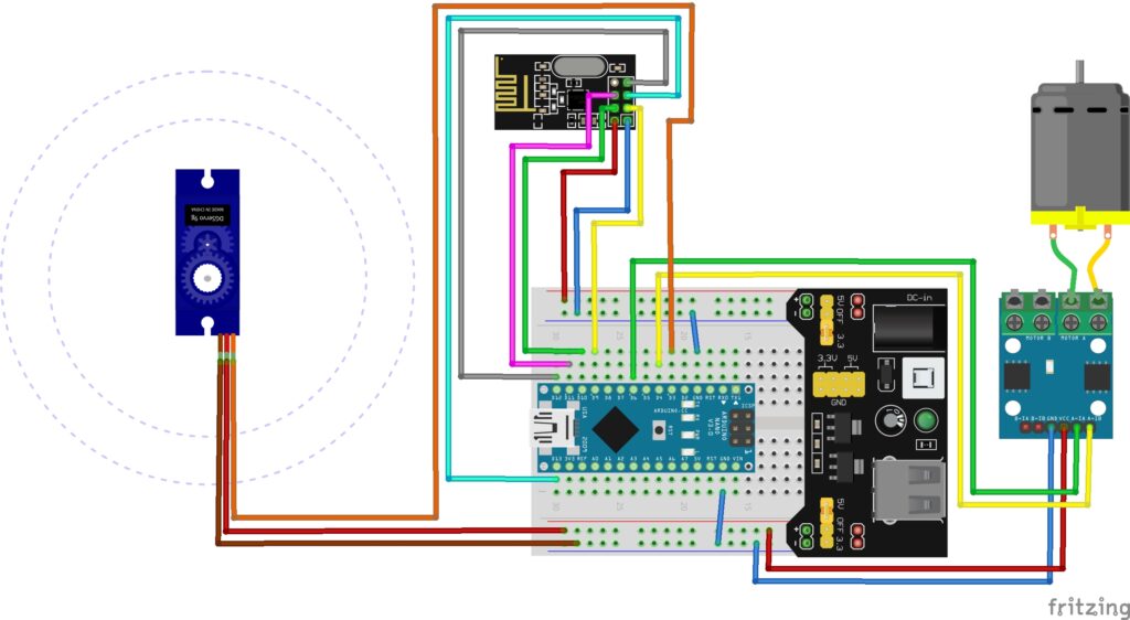
Pin Configuration:
Connect your Breadboard Power Supply to the breadboard making sure the (+) and (–) pins line up correctly with the red and blue rails on the breadboard. Also make sure the power supply is set to 5V by moving the jumpers to the correct position. Once the rest of the receiver is built you can then go ahead and connect a 9V battery to the breadboard power supply using the 9V battery barrel jack connector.
- NRF24L01:
- VCC on the NRF24L01 module to 3.3V on the Arduino (unless you are using the base board then you can connect it to 5V).
- GND on the NRF24L01 module to GND on the Arduino.
- CSN (Chip Select) on the NRF24L01 module to Digital pin 10 on the Arduino.
- CE (Chip Enabled) on the NRF24L01 module to Digital pin 9 on the Arduino.
- SCK (Serial Clock) on the NRF24L01 module to Digital pin 13 on the Arduino.
- MOSI (Master Out Slave in) on the NRF24L01 module to Digital pin 11 on the Arduino.
- MISO (Master in Slave Out) on the NRF24L01 module to Digital pin 12 on the Arduino.
- IRQ: This pin is optional and may be left unconnected as we won’t be using it for this guide. It is used for interrupt handling.
- L9110 Motor Driver:
- GND on the L9110 module to the Blue Rail (ground) on the Breadboard.
- VCC on the L9110 module to the Red Rail (live) on the breadboard.
- A-1A on the L9110 module to Digital pin 6 on the Arduino.
- A-1B on the L9110 module to Digital pin 4 on the Arduino.
- DC Motor:
- Connect the DC motor to the connector block ports for Motor A. (Polarity will only change the direction of the motor).
- Servo Motor:
- GND (typically the brown wire) on the servo motor to the Blue Rail on the breadboard.
- VCC (typically the red wire) on the servo motor to the Red Rail on the breadboard.
- Signal (typically the orange wire) on the servo motor to Digital pin 3 on the Arduino.
Pin labels may vary.
Arduino Code Example
Here is the code I used to control the receiver. Once you are ready, upload the code to the Receiver Arduino.
#include <SPI.h>
#include <RF24.h>
#include <Servo.h>

#define CE_PIN 9
#define CSN_PIN 10

RF24 radio(CE_PIN, CSN_PIN);

#define myServo 3
Servo servo;

// Motor Controller Pins
int EN1 = 5;
int IN1 = 4;
int IN2 = 6;

struct JoystickData {
  int x;
  int y;
};

void setup() {
  Serial.begin(9600);

  // Initialize the NRF24 module
  if (!radio.begin()) {
    Serial.println("Failed to initialize NRF24 module. Please check wiring.");
    while (1); // Loop indefinitely if initialization fails
  }

  // Set the receiving address
  radio.openReadingPipe(1, 0xF0F0F0F0E1LL);

  // Start listening for incoming messages
  radio.startListening();

  // Attach servo to a PWM-capable pin, for example, pin 5
  servo.attach(myServo);

  // Motor driver pins setup
  pinMode(EN1, OUTPUT);
  pinMode(IN1, OUTPUT);
  pinMode(IN2, OUTPUT);
}

void loop() {
  // Check if there's a message available
  if (radio.available()) {
    JoystickData joystickData;

    // Read the message from the NRF24 module
    radio.read(&joystickData, sizeof(joystickData));

    // Print the received joystick data to the serial monitor
    Serial.print("Received Joystick Data - X: ");
    Serial.print(joystickData.x);
    Serial.print(", Y: ");
    Serial.println(joystickData.y);


    // Control the DC motor based on X axis
    int motorSpeed = map(joystickData.x, 0, 1023, -255, 255); // Map joystick data to motor speed
    analogWrite(EN1, abs(motorSpeed)); // Control the motor speed
    if (motorSpeed > 50) {
      Serial.println("Motor Forwards");
      digitalWrite(IN1, HIGH); // Set motor direction
      digitalWrite(IN2, LOW);
    } else if (motorSpeed < -50) {
      Serial.println("Motor Backwards");
      digitalWrite(IN1, LOW); // Set motor direction
      digitalWrite(IN2, HIGH);
    } else{
      Serial.println("Motor Standby");
      digitalWrite(IN1, LOW); // Motor off
      digitalWrite(IN2, LOW);
    }


    // Control the servo based on Y axis
    int servoAngle = map(joystickData.y, 0, 1023, 0, 180); // Map joystick data to servo angle
    servo.write(servoAngle); // Set servo angle
  }
}
Breaking Down the Code
Now, let’s break down the receiver code step by step:
Step 1: Include Libraries
#include <SPI.h>
#include <RF24.h>
#include <Servo.h>
These lines include the necessary libraries for SPI communication, the NRF24L01 module, and servo control.
Step 2: Define Pins
#define CE_PIN 9
#define CSN_PIN 10
These lines define the pins used for the CE (Chip Enable) and CSN (Chip Select Not) of the NRF24L01 module.
Step 3: Create RF24 Object
RF24 radio(CE_PIN, CSN_PIN);
This line creates an instance of the RF24 class with the specified CE and CSN pins.
Step 4: Define Servo Pin
#define myServo 3
This line defines the pin used to control the servo motor.
Step 5: Create the Servo Object
Servo servo;
This line declares a Servo object named servo to control the servo motor.
Step 6: Define Motor Controller Pins
int EN1 = 5;
int IN1 = 4;
int IN2 = 6;
These lines define the pins used to control the DC motor connected to the motor controller.
Step 7: Define JoystickData Structure
struct JoystickData {
int x;
int y;
};
This defines a structure named JoystickData containing two integer variables for x and y joystick values.
Step 8: Setup Function
void setup() {
  Serial.begin(9600);

  // Initialize the NRF24 module
  if (!radio.begin()) {
    Serial.println("Failed to initialize NRF24 module. Please check wiring.");
    while (1); // Loop indefinitely if initialization fails
  }

  // Set the receiving address
  radio.openReadingPipe(1, 0xF0F0F0F0E1LL);

  // Start listening for incoming messages
  radio.startListening();

  // Attach servo to a PWM-capable pin
  servo.attach(myServo);

  // Motor driver pins setup
  pinMode(EN1, OUTPUT);
  pinMode(IN1, OUTPUT);
  pinMode(IN2, OUTPUT);
}
In the setup function:
- Serial communication is initialized at a baud rate of 9600.
- The NRF24 module is initialized, and if initialization fails, an error message is printed.
- The receiving address for the NRF24 module is set.
- The NRF24 module starts listening for incoming messages.
- The servo is attached to the specified pin, and motor controller pins are configured as outputs.
Step 9: Loop Function
void loop() {
  // Check if there's a message available
  if (radio.available()) {
    JoystickData joystickData;

    // Read the message from the NRF24 module
    radio.read(&joystickData, sizeof(joystickData));

    // Print the received joystick data to the serial monitor
    Serial.print("Received Joystick Data - X: ");
    Serial.print(joystickData.x);
    Serial.print(", Y: ");
    Serial.println(joystickData.y);

    // Control the DC motor based on X axis
    int motorSpeed = map(joystickData.x, 0, 1023, -255, 255); // Map joystick data to motor speed
    analogWrite(EN1, abs(motorSpeed)); // Control the motor speed
    if (motorSpeed > 50) {
      Serial.println("Motor Forwards");
      digitalWrite(IN1, HIGH); // Set motor direction
      digitalWrite(IN2, LOW);
    } else if (motorSpeed < -50) {
      Serial.println("Motor Backwards");
      digitalWrite(IN1, LOW); // Set motor direction
      digitalWrite(IN2, HIGH);
    } else {
      Serial.println("Motor Standby");
      digitalWrite(IN1, LOW); // Motor off
      digitalWrite(IN2, LOW);
    }

    // Control the servo based on Y axis
    int servoAngle = map(joystickData.y, 0, 1023, 0, 180); // Map joystick data to servo angle
    servo.write(servoAngle); // Set servo angle
  }
}
In the loop function:
- It checks if there’s a message available from the NRF24 module.
- If a message is available, it reads the joystick data into the
joystickDatavariable. - It prints the received joystick data to the Serial monitor.
- It maps the joystick data to control the speed and direction of the DC motor.
- Based on the mapped motor speed, it sets the direction of the motor using the motor controller pins.
- It also maps the joystick data to control the angle of the servo motor.
Mission Success?
You should now have complete control of your receiver Arduino via the Transmitter Arduino. If you have not got this working correctly then double check all connections as a loose wire will almost certainly be the problem. If you have any questions, please feel free to ask and I will happily try and answer them all!
Conclusion
Congratulations on completing this guide on wireless control of Arduino devices using NRF24L01 radio modules! You’ve learned how to establish reliable communication between two Arduino boards, enabling remote control of a servo motor and a DC motor with ease.
By following the step-by-step instructions and understanding the code explanations, you’ve gained valuable insights into wireless communication protocols and motor control techniques. With this knowledge, you can expand and customize your projects to suit a wide range of applications, from robotics to home automation.
We hope this guide has inspired you to embark on new projects and deepen your understanding of electronics and programming. If you have any questions or ideas for future projects, don’t hesitate to reach out!
That’s All Folks!
“Disclosure: This post contained Amazon weblinks. We are a participant in the Amazon Services LLC Associates Program, an affiliate advertising program designed to provide a means for us to earn fees by linking to Amazon.co.uk and affiliated sites. This means that when you click on product links and make a purchase on Amazon, we may receive a small commission at no extra cost to you. We only recommend products that we genuinely believe in, and think will be of value to our readers. Your support through these links helps us continue to provide quality content to you. Thank you for your support!“