

What is the D1-Mini?
The D1 Mini is a compact development board based on the ESP8266 Wi-Fi module. It’s designed to make it easy for developers and makers to build IoT (Internet of Things) projects with Wi-Fi connectivity.
Key Features:
ESP8266 Wi-Fi Module: The D1 Mini is built around the ESP8266, which is a highly integrated chip with Wi-Fi capabilities. It’s known for its low cost and low power consumption, making it ideal for IoT projects.
Compact Size: One of the notable features of the D1 Mini is its small form factor. It’s about the size of a typical Arduino Pro Mini, making it suitable for projects with limited space.
USB Connectivity: The D1 Mini typically comes with a built-in micro USB connector, which can be used for both power and programming. This makes it easy to connect to a computer for programming and debugging.
GPIO Pins: The D1 Mini board exposes several GPIO (General Purpose Input/Output) pins, allowing you to connect various sensors, displays, and other peripherals to your project. These pins are compatible with Arduino libraries, making it relatively easy to program.
Built-in Wi-Fi: The primary purpose of the ESP8266 module is to provide Wi-Fi connectivity. This allows your project to connect to the internet or a local network, enabling remote control and data exchange.
Arduino IDE Support: You can program the D1 Mini using the Arduino IDE, which is a popular development environment for microcontroller-based projects. There are plenty of libraries and resources available for the ESP8266, making it relatively easy to get started.
NodeMCU and MicroPython Support: In addition to Arduino, you can also use NodeMCU firmware or MicroPython on the D1 Mini. These options provide different programming languages and capabilities for your projects.
I2C and SPI Support: The D1 Mini also features I2C and SPI pins, allowing you to interface with sensors and displays that use these communication protocols.
Built-in LED: There is usually a built-in LED on the D1 Mini that you can control programmatically, which can be useful for debugging and indicating the board’s status.
Open-Source: The D1 Mini is an open-source platform, which means you can find schematics, documentation, and community support online.
D1-Mini Pins
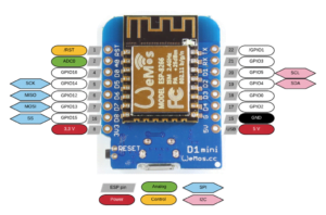
The D1-mini pins look the same as regular Arduino pins but they are not, Pin D1 on the D1-Mini is not pin 1 on the Arduino, it would be pin 5. This can be really confusing at first, but luckily to make things easier we can declare the D1-Mini’s digital pins like “D1” in the IDE. From the D1-mini pin out diagram we can see that SCL is D1, and SDA is D2 for I2C components, and D5-D8 for SPI. There is also only 1 Analog pin on D1-mini just like all other ESP8266 boards.
How to use the D1-Mini with Arduino IDE
Step 1: Add the ESP8266 Board Manager:
The D1 Mini is based on the ESP8266, so you’ll need to add support for the ESP8266 boards to the Arduino IDE. Here’s how:- Open the Arduino IDE.
- Go to “File” > “Preferences.”
- In the “Additional Boards Manager URLs” field, add this URL: http://arduino.esp8266.com/stable/package_esp8266com_index.json
- Click “OK” to save the preferences.
Step 2: Install the ESP8266 Board Package:
- Go to “Tools” > “Board” > “Boards Manager.”
- In the search bar, type “esp8266” and press Enter.
- Click on “esp8266 by ESP8266 Community” and click the “Install” button.
Step 3: Select the D1 Mini Board:
- After the installation is complete, go to “Tools” > “Board” and select “LOLIN(WEMOS) D1 R2 & mini.”
- Choose the appropriate Flash Size and Upload Speed settings for your D1 Mini board. The default settings should work in most cases.
Step 4: Select the COM Port:
- Go to “Tools” > “Port” and select the COM port that corresponds to your D1 Mini. If you’re unsure which port to select, you can check it in the Device Manager (Windows) or System Information (macOS).
Step 5: Write and Upload Code:
Now, you can write your Arduino sketch and upload it to the D1 Mini:- Write your Arduino sketch in the IDE.
- Click the “Upload” button (the right-pointing arrow) in the IDE to compile and upload your sketch to the D1 Mini.
- Wait for the upload process to complete. You should see status messages in the IDE’s console.
Step 6: Monitor Serial Output:
To debug your code and view serial output, you can use the Serial Monitor:- Go to “Tools” > “Serial Monitor.”
- Set the baud rate to match the one specified in your sketch (usually 115200).
- You should see any serial output from your D1 Mini in the Serial Monitor.
That’s it! You’ve successfully set up the Arduino IDE for programming the D1 Mini. You can now start creating and uploading your own Arduino sketches to the board. Make sure to refer to the D1 Mini pinout diagram and documentation for specific details on its GPIO pins and capabilities when working on your projects.
Let's Build!
Simple LED Circuit:
Starting simple, we are going to make a LED blink.
The Code:
int LED = D4;

void setup() {
  pinMode(LED,OUTPUT);
}

void loop() {
  digitalWrite(LED,HIGH);
  delay(500);
  digitalWrite(LED,LOW);
  delay(500);
}
The Circuit:
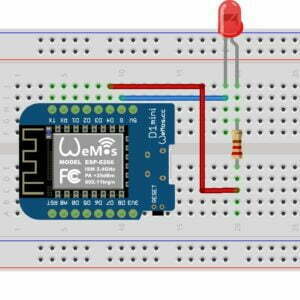
This is a very basic circuit with just 2 components and the D1-Mini. Assemble the components just like in the image shown below.
- Connect the long leg of the Led to Pin D4 on the D1-Mini using a 220 Ohm current limiting resistor in between.
- Connect the short leg of the LED to G (ground) on the D1-mini.
Upload the Code:
Once you have built the circuit, upload the code to the D1-mini board. The LED should start blinking on and off.
Interfacing the D1-Mini with the Mini-OLED
Now we are going to connect a Mini-OLED display to the D1-mini, and then display the Hello World print statement.
The Code:
#include <Wire.h>
#include <Adafruit_SSD1306.h>
#include <Adafruit_GFX.h>

Adafruit_SSD1306 display(128, 64, &Wire);

void setup() {
  if(!display.begin(SSD1306_SWITCHCAPVCC, 0x3C)) {
    Serial.println(F("SSD1306 allocation failed"));
  }
  display.setTextSize(2);
  display.setTextColor(WHITE);
  display.display();
  delay(2000);
}

void loop() {
  display.clearDisplay();
  display.setCursor(30,15);
  display.println("Hello");
  display.setCursor(40,40);
  display.println("World");
  display.display();
  display.clearDisplay();
  delay(1000);
}
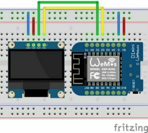
The Circuit:
- Connect the mini-OLEDs GND pin to the G pin on the D1-Mini.
- Connect the Mini-OLEDs VCC pin to the 5V pin on the D1-Mini.
- Connect the Mini-OLEDs SCL pin to the D1 pin on the D1-Mini.
- Connect the Mini-OLEDs SDA pin to the D2 pin on the D1-Mini.
Just like in the circuit shown below:
Upload the Code:
Once you have the circuit built, upload the code to the D1-mini. Once the code finishes uploading to the board, you will be greeted with the Hello World message printed on your Mini-OLED display.
If you want to learn more about the Mini-OLED, please read our guide on How to use the Mini-OLED with Arduino to find out everything you need to know about programming with the Mini-OLED display.
Conclusion
The ESP8266 D1 Mini is a versatile and affordable board for IoT projects, home automation, and more. It’s a great choice for makers and developers looking to add Wi-Fi capabilities to their projects without the complexity of full-sized development boards. The D1-mini will open up so many more options for our Arduino projects, I can’t wait to see what else we create in the future.
Recommendations:
The Elegoo Super Starter Kit
If you don’t already own any Arduino hardware, we highly recommend this kit as it has everything you need to start programming with Arduino. You can find out more about this kit, including a list of its components here: Elegoo Super Starter Kit
You can find this kit on Amazon here: Elegoo Super Starter Kit
The 0.96-inch Mini-OLED Display
We highly recommend this mini-OLED bundle of five 0.96-inch OLED displays. We have bought these before and they all worked perfectly. You can read more about the mini-OLED here: Mini-OLED
You can find this bundle on Amazon here: OLED Displays
Elegoo Nano (Arduino Compatible)
We have bought these Nano boards many times and can highly recommend them. There are three Nano boards in this pack making them a total bargain for everyone.
You can find this pack on Amazon here: Arduino Nano
ESP8266 D1-Mini
D1-Mini is an Arduino compatible Wi-Fi board based on an ESP-8266-12F. This WLAN board has 9 digital I/O pins.
You can find this board on Amazon here: D1-Mini